Fixing Holder for Vibration Generating Device

a technology for fixing holders and vibration generators, which is applied in the direction of mechanical energy handling, supports/enclosements/casings, dynamo-electric machines, etc., can solve the problems of difficulty in obtaining a sufficient level of vibration for users, and achieve the effect of reducing the thickness of mobile communication devices, reducing costs, and easy modification of design

Inactive Publication Date: 2007-11-01
NAMIKI PRECISION JEWEL CO LTD
View PDF11 Cites 20 Cited by
  • Summary
  • Abstract
  • Description
  • Claims
  • Application Information

AI Technical Summary

Benefits of technology

[0020] As described above, the mounting holder according to Claim 1 enables the mounting of the device for generating vibration in a space made by cutting off a circuit board mounted inside a housing of a portable apparatus at an arbitrary vertical position against the circuit board surface and holding or including a part of an outer periphery of the device for generating vibration. The arbitrary position means that a ratio of upper and lower dimensions of the device for generating vibration positioned against the circuit board is adjustable, and an offset value of the circuit board position from the central axis of the device for generating vibration can be calculated from this ratio.
[0021] More specifically, a ratio of an upper dimension to a lower dimension of the device for generating vibration against the surface of the circuit board 50 can be freely adjusted when designing the parts of the circuit board depending on the dimensions of neighboring electronic parts, for example, so as to be F to G, E to E, and H to J shown in (a), (b), and (c) of FIG. 1. Thus a thickness of a mobile communications device can be further reduced, a device for generating vibration can be mounted in a housing without a size reduction, and a vibration force identical to that of a conventional device for generating vibration can be obtained without changing a diameter of a weight 6.
[0022] In addition to the effect according to Claim 1, the mounting holder according to Claim 2 can hold a device for generating vibration at an arbitrary vertical position against a circuit board in the holder by providing groove-like rail sections to both sides of the holder at the same vertical position and inserting internal side edges of the cut off circuit board or parts of a housing of a portable apparatus into the groove-like rail sections.
[0023] More specifically, the edges of the cut off circuit board 50 can be inserted into the groove-like rail sections U provided at an arbitrary vertical position of the sides of the holder 3 to fix the device for generating vibration at an arbitrary vertical position, for example, as shown in FIGS. 2 and 3. In this case, it is possible to use the device for generating vibration in different models simply by changing a power supply terminal 4 mounted to a connecting section 4e and the position of the grooves of the holder 3 itself without changing the basic design of the main unit of the device for generating vibration to easily change the design depending on a model change of a mobile communications device while substantially reducing costs.
[0024] In addition to the effect according to Claim 1 or 2, the invention according to Claim 3 provides a mounting holder, wherein a power supply land of the circuit board and a power supply terminal of the device for generating vibration are firmly pressed onto each other using the elasticity of a mounting component used as a holder by an action of assembling the split device housing so as to be electrically connected when the device for generating vibration is installed on the circuit board inside the device housing.
[0025] More specifically, when a device for generating vibration 1 is installed on a circuit board 50, a power supply terminal 4 is pressed onto a power supply land 55 of the circuit board 50 so as to be firmly connected to the inside of the device for generating vibration electrically by holding the holder 3 inside a housing of the device main unit by the circuit board 50 using groove-like rail sections, for example, as shown in FIGS. 1, 2 and 3. Moreover, when the device for generating vibration 1 is arranged inside the device main unit, it is possible to reduce contact friction between the power supply land 55 of the circuit board 50 and a contact section of the power supply terminal 4 to solve such problems as insufficient continuity.

Problems solved by technology

Moreover, there were many problems in a mounting method of the vibration motor 102 such that it is difficult to obtain a sufficient level of vibration for a user because a diameter of an eccentric weight 106 was decreased along with a decrease in a diameter of the vibration motor 102.

Method used


Image

  • Fixing Holder for Vibration Generating Device
  • Fixing Holder for Vibration Generating Device
  • Fixing Holder for Vibration Generating Device

Examples


first embodiment

[0033] Configuration of the first embodiment according to the invention is hereafter described while referring to FIGS. 1 through 4. In this first embodiment, a coreless type cylindrical vibration motor having a rotation shaft attached with an eccentric weight is explained as an example of an embodiment of a device for generating vibration. Also, a vibration motor 2 according to this embodiment has a structure in which an entire power supply mechanism including a terminal block 11 (especially a connecting section 4e) is arranged close to a weight 6 in a central section of a motor body as shown in FIGS. 4 and 9, differing from a conventional motor structure shown in FIGS. 7 and 8.

[0034] An eccentric weight 6 is attached to an end of a rotation shaft 5 of this vibration motor 2, and a rotor section for driving the rotation shaft 5 is accommodated and arranged inside a housing 13 while supported by bearings 9. A motor drive mechanism mainly consists of the housing 13 of a stator, the ...

second embodiment

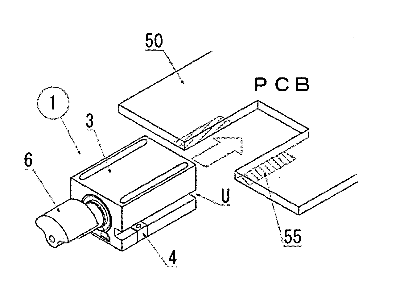
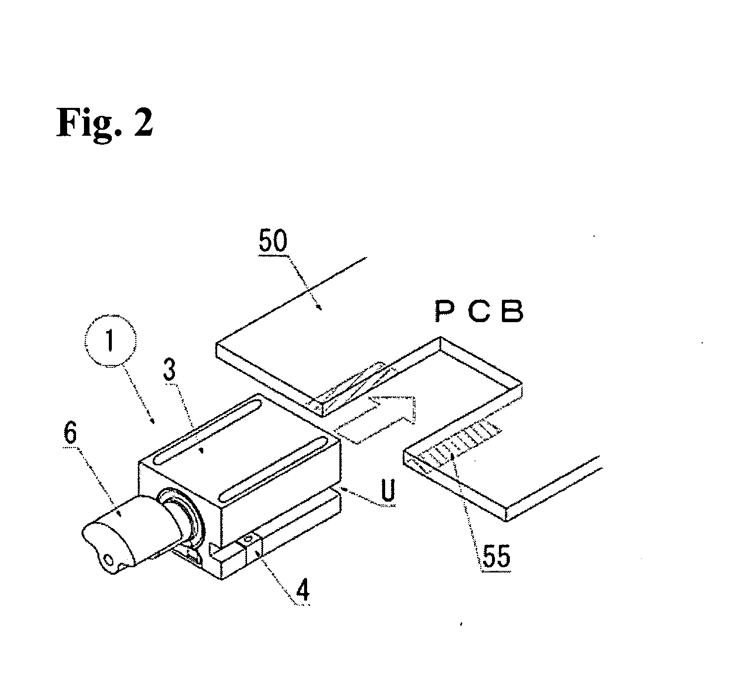
[0040] Now, the configuration of the second embodiment according to the invention is described while referring to FIGS. 5 and 6. In this second embodiment, a general cylindrical vibration motor having a rotation shaft attached with an eccentric weight is described as an embodiment of a device for generating vibration. A vibration motor according to this embodiment has a structure in which a power supply mechanism is located at an opposite side of a weight 6 and power supply terminals 40 axially protrude from an end surface of a cylindrical motor body.

[0041] The circuit board 50 has a cut off space as shown in FIG. 5. Solder reflow fixing surfaces 56 that can be soldered are arranged on both sides of the cut off space close to the internal side edges, and power supply lands 55 connected to power supply terminals 40 are mounted on the surface of the circuit board 50 common to the solder reflow fixing surfaces. A vibration motor 20 has a holder, wherein wing-shaped protrusions 30R mad...


PUM


Abstract

[PROBLEMS] To provide a fixing structure capable of adjusting the dimensions in the vertical direction of a vibration generating device including a circuit board in combination with the circuit board without reducing the size or the diameter of the vibration generation device.
[MEANS FOR SOLVING PROBLEMS] A fixing holder in a holder shape for holding or including at least a part of the outer circumference of a vibration generating device has an inner circumferential surface substantially identical to the external shape of the vibration generating device. Groove-like rail parts are provided partially in the outer circumferential surface of the holder at the opposite ends thereof in the same linear direction, and the side end part of a notched circuit board or a part on the housing side of the apparatus is inserted into each of the groove-like rail parts, thus holding and securing the vibration generating device at an arbitrary vertical position against the surface of the circuit board in the apparatus.

Description

TECHNICAL FIELD [0001] This invention relates to a device for generating vibration that is mainly mounted in a portable apparatus (including such electronic devices as a mobile phone, a PHS, a small wireless communications device, and other various portable information communications terminals) to perform a soundless alarm function, specifically to a holding structure of a circuit board in a housing of a portable communication device and the device for generation vibration mounted on the circuit board, and a fixing holder to position the fixing point of the device for generation vibration. BACKGROUND ART [0002] A sudden incoming ring tone of a portable apparatus may sometimes disturb others in, for example, a quiet public space such as an art gallery and a concert hall with many people in a room for important commercial negotiations or conferences. Therefore, a wireless alarm function using a device for generating vibration to report an incoming signal with sensible vibration (gener...

Claims


Application Information

Patent Timeline
Patent Type & Authority Applications(United States)
IPC IPC(8): H05K7/12
CPCH02K5/00H02K2211/03H02K7/061H02K5/225
Inventor UCHIUMI, HIDEHIROMORITA, KAZUO
Owner NAMIKI PRECISION JEWEL CO LTD
Why Eureka
Try Eureka