
Method of and apparatus for image serving

a technology of image file and image, applied in the field of image file transfer, can solve the problems of insufficient image market optimization, almost certainly wrong appearance, and inability to effectively use small amounts of pistol in the hands of actors, so as to avoid data split up and effective use

Inactive Publication Date: 2007-11-01
PANDORA INT
View PDF5 Cites 10 Cited by
  • Summary
  • Abstract
  • Description
  • Claims
  • Application Information

AI Technical Summary

Benefits of technology

[0025] By predicting the next tile that may be required and transmitting the image data using otherwise unused capacity, the performance of the image serving is increased, as the operator will not need to separately recall the predicted tile, but instead it is available to be used without any losses or excess loading compared to the situation where the unused capacity on the link remains unused.
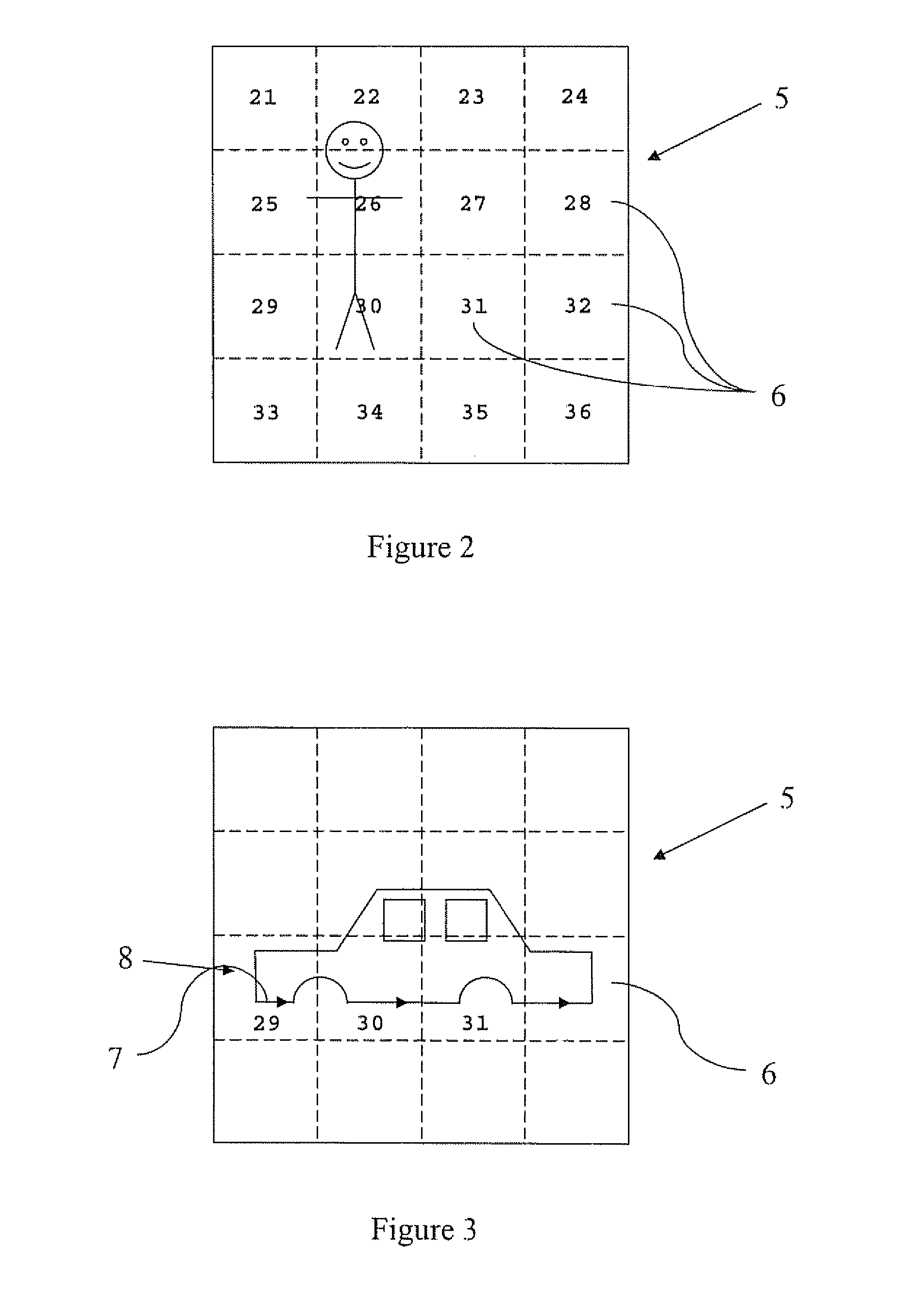
[0027] By predicting the required image tiles in this way, the operator can work on tiles at varying positions in the image, and across a sequence of frames, whilst minimising the loading on the communications link, and also minimising the time spent waiting by the operator for the next tile required.
[0029] By queuing up a series of potentially required tiles the unused capacity or bandwidth of the communications link can be most effectively utilised. For example, when there is sufficient capacity to send an appropriate adjacent tile, and a corresponding tile in a following frame, as well as an adjacent tile in the following frame, then there is a greater range of options which the operator can take which will result in no new tiles being required to be transmitted. In the best case, the communications link is utilised at maximum capacity at all times, thus ensuring that no waste occurs.
[0033] This allows tiles to be automatically sent to the client terminal in accordance with the way the operator is editing the image. By manually or automatically identifying a point of interest the system can decide more effectively which tiles are required, both in the same frame and in following frames.
[0036] This ensures that the remaining spare capacity can be most effectively utilised, as it will be as large as possible in each channel, and the need to split up data is avoided.

Problems solved by technology

Images have substantially different properties than typical data in Client Server architectures, by virtue of being of many megabytes per frame, which is made worse by the use of multiple framed motion imagery rather than still imagery.
Yet because the use of Client Server architectures are primarily for non-image markets, the systems developed are by no means optimal for image markets, where the data occurs in such large ‘records’.
This will almost certainly look wrong if the cut outline is specified at the scaled resolution and not the full resolution.
The visibility of small amounts of the pistol in the actor's hands would look totally wrong.
This can lead to delays in the image editing process, as the operator will have to wait for each tile to be downloaded once work has finished on the preceding tile, or a tile may be required at a time when the server or the server-client link has no spare capacity.

Method used


Image

  • Method of and apparatus for image serving
  • Method of and apparatus for image serving
  • Method of and apparatus for image serving

Examples


Embodiment Construction

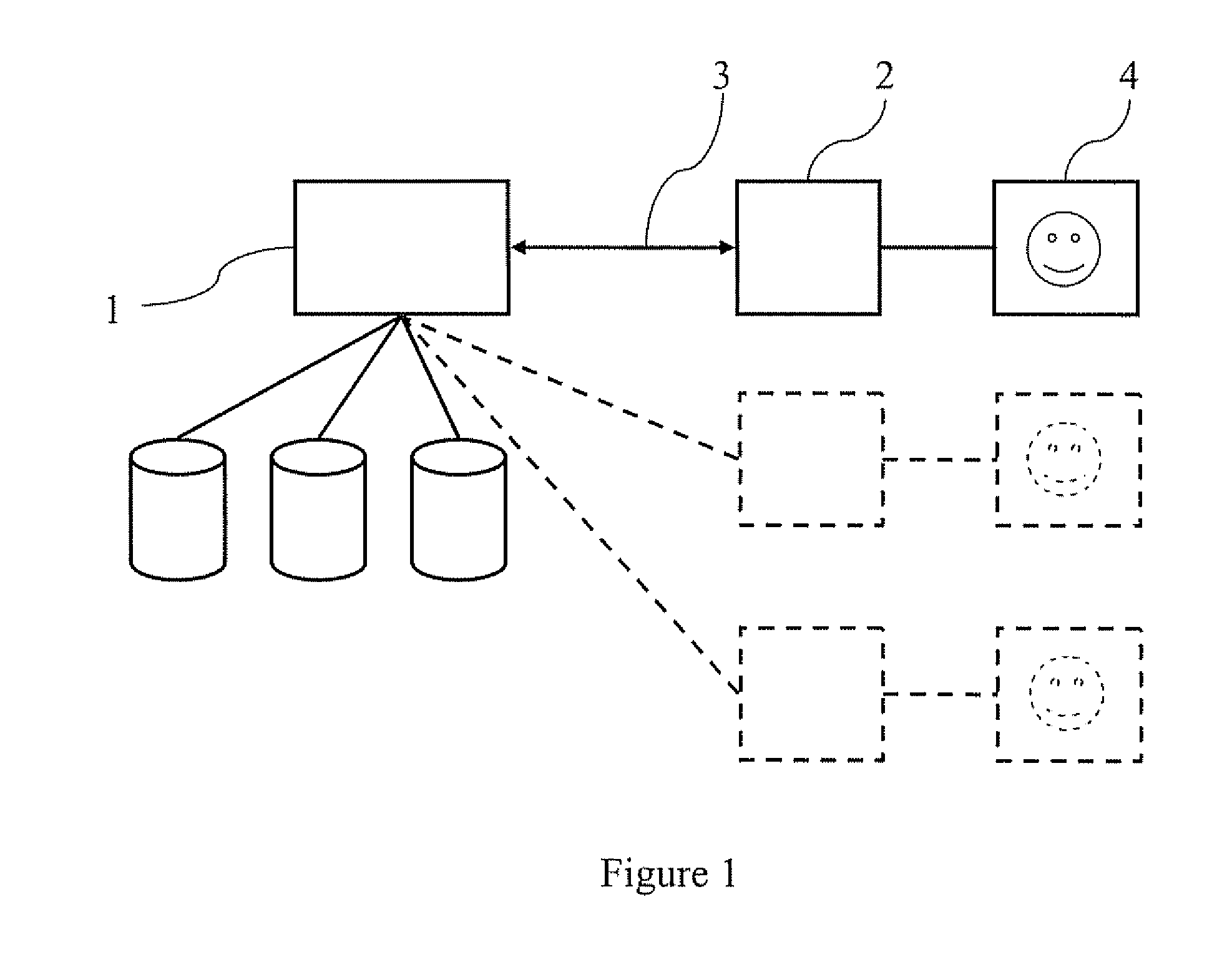
[0046]FIG. 1 shows a typical client-server architecture. A server 1 is connected to a client 2 by a link 3. The client 2 has a display screen 4 upon which the image is shown. Further clients could be connected to the server 1 as indicated by the dashed lines. In image serving, the requirement in terms of data transfer per second is generally much higher than with commercial clerical systems. A typical architecture has multiple channels or ‘pipes’ between points as the client-server links 3. Each of these ‘pipes’ has a maximum data transfer capacity.

[0047] One architecture we have found suitable to build such systems is manufactured by Picolight Incorporated of 1480 Arthur Ave Louisville, CO 80027 USA (www.picolight.com). The model used transmits data at a rate of 3.125 Gbits per second on each channel or pipe and we have used twelve of these pipes together, giving a total data capacity of 37.5 Gbits per second. It is necessary to utilise substantial buffering at each transceiver, a...


PUM


Abstract

A method of transmitting images from a server to a client along a communications link, comprises the steps of: dividing a relatively high resolution image into a plurality of lower resolution tiles; transmitting a first image tile to a client terminal for editing; predicting at least one further image tile to be required; and transmitting the at least one predicted tile to the client terminal using unused capacity on the communications link.

Description

FIELD OF THE INVENTION [0001] The present invention relates to a method and apparatus for image file transfer from a server to a client. BACKGROUND TO THE INVENTION [0002] Client-server architectures for computing purposes have been known for at least thirty years. Such architectures commonly feature a large computer, known as a ‘server’ with significant amounts of storage ‘feeding’ many terminals or ‘clients’ with data. One common usage may be in a financial institution or bank, where all the customer records are contained within the server and when an employee of the bank wishes to inspect a customer's records, the employees' computer (a ‘terminal’ or ‘client’) requests over a data link of some form that a given customers' records are recalled by the server computer, and passed back over the link to the client computer, where the employee can view such data. The importance of such architectures are that only one set of customer data is needed—it is not necessary for every employee...

Claims


Application Information

Patent Timeline
IPC IPC(8): G06K9/36G06F15/16
CPCH04L67/06H04N19/593H04N19/51G06F16/51G06T1/60H04N5/262
Inventor BRETT, STEPHEN DAVID
Owner PANDORA INT
Learn More