Process and device for sterilising ambient air

a technology of ambient air and process, which is applied in the direction of ohmic-resistance heating devices, heating types, applications, etc., can solve the problems of rising reaction speed with formed oxygen species on the surface of activated carbon, restricted application and inability to adapt to a field of known devices and processes

Inactive Publication Date: 2007-11-01
SCHRODER WERNER
View PDF8 Cites 84 Cited by
  • Summary
  • Abstract
  • Description
  • Claims
  • Application Information

AI Technical Summary

Benefits of technology

[0036] According to a further preferred embodiment, a zigzag arrangement of the catalyst container allows the wall thickness thereof, and thus also the flow resistance thereof, to be reduced at a predetermined volume.
[0037] It has been found that the devices on which the solutions according to the invention are based can be used effectively in ventilation systems in order lastingly to sterilise the ambient air conducted therein, as the air flow rate required for this purpose can be achieved. For conventional commercial air-conditioning systems, provision is made, for example, for the ambient air filling the room to be ventilated to be circulated several times per hour.

Problems solved by technology

This increases the concentration of these components compared to the gas phase, leading to a rise in the speed of reaction with the formed oxygen species on the surface of the activated carbon.
A drawback of the known devices and processes is the restricted field of application.
On account of their low throughputs, in particular, the known devices and processes are not suitable for a field of application of this type.

Method used


Image

  • Process and device for sterilising ambient air
  • Process and device for sterilising ambient air
  • Process and device for sterilising ambient air

Examples


second embodiment

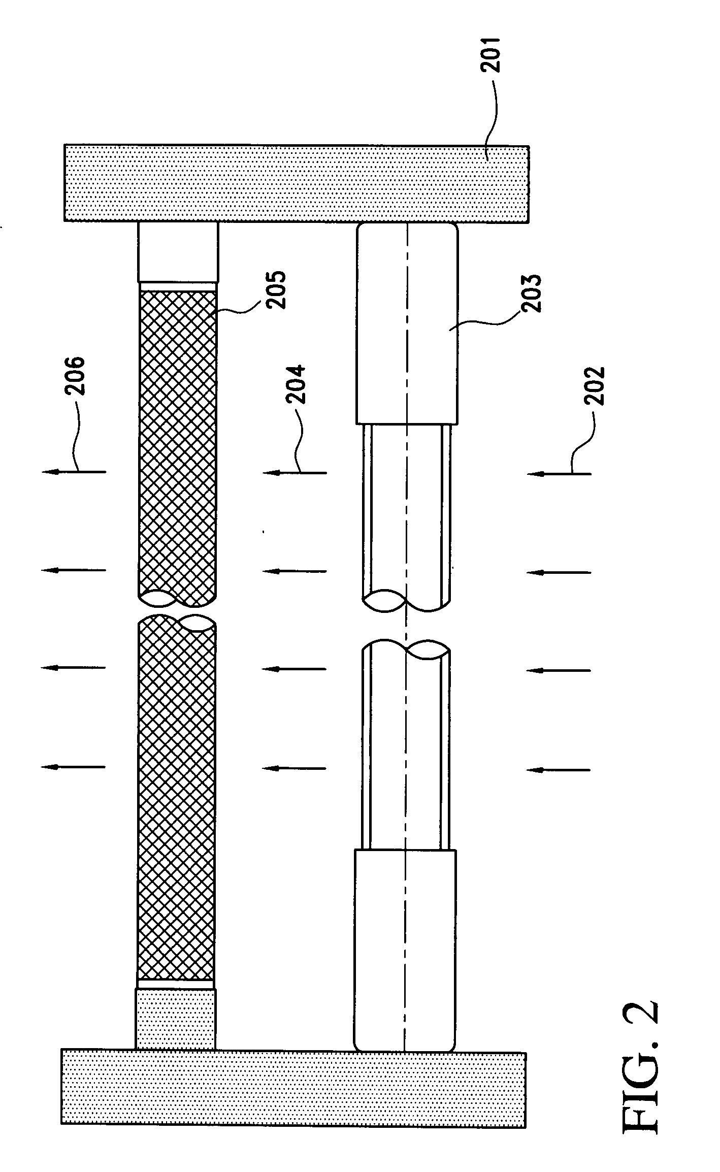
[0063]FIG. 4 is a cross section of an air duct with the arrangement of three portions according to a A UV tube 403, a catalyst 405 and an ionisation tube 407 are connected directly between the walls of the air duct 401. The entering ambient air 402 initially flows around one or more UV tubes 403. The ambient air 404 thus pre-treated then flows through the catalyst 405. Finally, the ambient air 406 thus further treated flows around one or more ionisation tubes 407 before the ambient air 408 then issuing can be further conveyed as purified and sterilised air in the air duct 401.

third embodiment

[0064]FIG. 5 is a cross section of an air duct with the arrangement of three portions according to a A UV tube 503, a catalyst 506 comprising a filter 505 for microorganisms and an ionisation tube 508 are connected directly between the walls of the air duct 501. The entering ambient air 502 flows initially around one or more UV tubes 503. The ambient air 504 thus pre-treated then flows through the filter 505 and the catalyst 506. The filter 505 holds off the microorganisms still contained in the ambient air 504, an additional sterilising effect being achieved as a result of the continuous irradiation of the filter by the UV tubes. Finally, the ambient air 507 thus further treated flows around one or more ionisation tubes 508 before the ambient air 509 then issuing can be further conveyed as purified and sterilised air in the air duct 201.

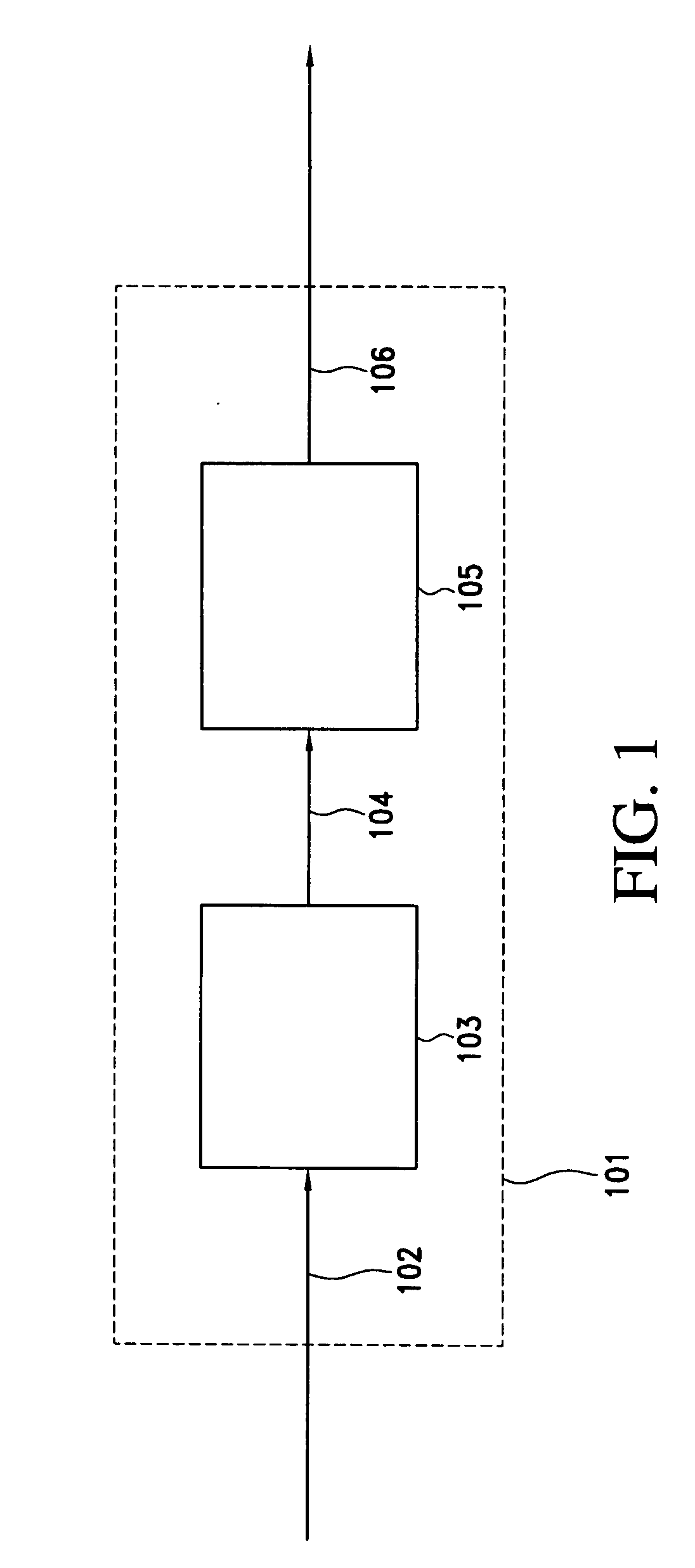
[0065]FIG. 6 is a block diagram in which the sterilising system according to the invention is connected in an air-conditioning system. The illustr...

fourth embodiment

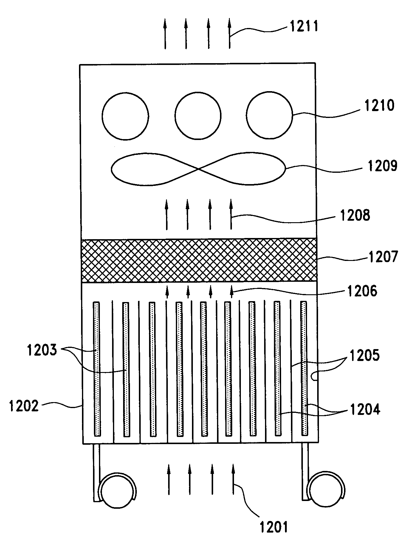
[0067] However, for high volume flow rates, it has also proven beneficial to arrange the UV emitters and ionisation tubes shown in FIG. 2, FIG. 4 and FIG. 5 not transversely but rather longitudinally to the air stream. FIG. 7 is a is perspective view of three portions 701, 702, 703 connected in series which provides for the UV emitters and ionisation tubes to be arranged longitudinally to the air stream. The three portions 701, 702, 703 are designed as box-type inserts which can be inserted into a rectangular air duct. The first portion comprises a large number of honeycomb reaction channels 704 connected in parallel. A UV emitter is arranged longitudinally in each of the reaction channels of the first portion. The first portion is followed by the second portion containing the catalyst 702. The catalyst can, for example, consist of activated carbon material as described hereinbefore. In the illustrated embodiment, the catalyst consists of a thin-walled construction fitted into the ...


PUM

PropertyMeasurementUnit
wavelength rangeaaaaaaaaaa

Abstract

A process is disclosed for sterilising ambient air conducted in an air duct (401), as well as a use of a device for breaking down gaseous hydrocarbon emissions in order to sterilise ambient air conducted in an air duct (104), and a device for sterilising ambient air conducted in an air duct (401). Ambient air is supplied to the air duct (401) of an UV unit (403) for irradiation with UV radiation, and the thus pre-purified ambient air is supplied to a downstream ionization unit (407) arranged in the air duct and in which the ambient air is ionised.

Description

RELATED APPLICATIONS [0001] This is a continuation application of International Application No. PCT / EP2005 / 011196, filed Oct. 18, 2005, which claims the priority benefit of Germany Patent Application No. DE 10 2004 050 657.4, filed Oct. 18, 2004 and Germany Patent Application No. DE 10 2005 003 923.5, filed Jan. 27, 2005, all of which are incorporated herein by reference.FIELD OF THE INVENTION [0002] The invention relates to a process for sterilising ambient air conducted in an air duct, to a use of a device for breaking down gaseous hydrocarbon emissions in order to sterilise ambient air conducted in an air duct, and to a device for sterilising ambient air conducted in an air duct. BACKGROUND OF THE INVENTION [0003] EP 0 778 070 B1 discloses a device for breaking down gaseous hydrocarbon emissions in an air duct, by means of which pollutant-containing exhaust air is discharged. In the known device, at least one UV emitter, which exposes the exhaust air to UV radiation having a wave...

Claims


Application Information

Patent Timeline
Patent Type & Authority Applications(United States)
IPC IPC(8): A61L9/20
CPCA61L9/015A61L9/16A61L9/205H05B3/0052B01D53/007B01D53/8675F24F2003/1667A61L9/22B01D53/869B01D2257/91B01D2258/06B01D2259/4508B01D2259/804F24F8/22Y02A50/20
Inventor SCHRODER, WERNER
Owner SCHRODER WERNER
Why Eureka
Try Eureka