
Implantable medical electrical stimulation lead with distal fixation and method

a technology of medical electrical stimulation and implantable leads, which is applied in the field of system and method, can solve the problems of poor stimulation, low success rate of surgical procedures, and high likelihood of electrode dislocation, and achieves the effects of improving the safety and stability of patients, and improving the safety of patients

Inactive Publication Date: 2007-11-01
MEDTRONIC INC
View PDF29 Cites 64 Cited by
  • Summary
  • Abstract
  • Description
  • Claims
  • Application Information

AI Technical Summary

Benefits of technology

[0012] Yet other aspects in accordance with principles of the present invention relate to a method of providing electrical stimulation to bodily tissue of a patient at a stimulation site via a power source external the patient. The method includes providing an implantable medical electrical lead including a lead body and a fixation assembly. The lead body includes a wire and an electrically non-conductive material. The wire defines a distal portion terminating at a distal end and a proximal portion terminating at a proximal end. The wire forms a wound coil along at least the distal portion. The non-conductive material covers at least a section of the distal portion, terminating proximal the distal end of the wire coil. With this arrangement, an uncovered distal region of the wire coil is defined, characterized by the absence of the non-conductive material, with at least a segment of the uncovered distal region serving as a lead electrode. The fixation assembly is coupled to the uncovered distal region and includes at least one fixation member. In this regard, the fixation assembly is configured and assembled to the wire coil so as to define, and be transitionable between, a first, contracted state and a second, expanded state, with a radially outward extension of the fixation member relative to the wire coil being greater in the expanded state. The lead body is slidably disposed within a needle lumen having a diameter of no greater than 0.05 inch. In this regard, the fixation assembly is in the contracted state when the lead body is within the needle lumen. A distal tip of the needle is percutaneously directed toward the stimulation site. The lead body is deployed from the distal tip to implant the lead body at the stimulation site. The fixation assembly transitions from the contracted state to the expanded state. The needle is proximally withdrawn from the lead such that the proximal portion of the wire is external the patient. The proximal end of the wire is electrically coupled to a power source external the patient. In this regard, following implantation, the fixation assembly in the expanded state inhibits axial retrograde migration of the lead body from the stimulation site. In some embodiments, the fixation assembly self-transitions to the expanded state by the fixation member absorbing bodily fluids. In other embodiments, the fixation assembly self-transitions to the expanded state by the fixation member being released relative to the wire coil once the lead body exits the needle lumen. In yet other embodiments, the method is performed as part of a peripheral sacral nerve stimulation procedure, with the distal tip of the needle being directed into a sacral foramen.

Problems solved by technology

Many pharmaceuticals do not adequately resolve the issue and can cause unwanted side effects; further, a number of surgical procedures have a low success rate and / or are not reversible.
For example, any pulling or tugging on the proximal end of the lead body (from outside of the patient's body) could be directly communicated to the lead's electrode, thus creating a higher likelihood of electrode dislodgement and poor stimulation.

Method used


Image

  • Implantable medical electrical stimulation lead with distal fixation and method
  • Implantable medical electrical stimulation lead with distal fixation and method
  • Implantable medical electrical stimulation lead with distal fixation and method

Examples


Embodiment Construction

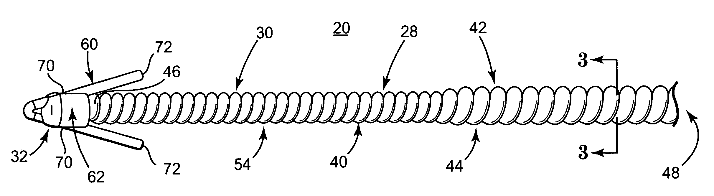
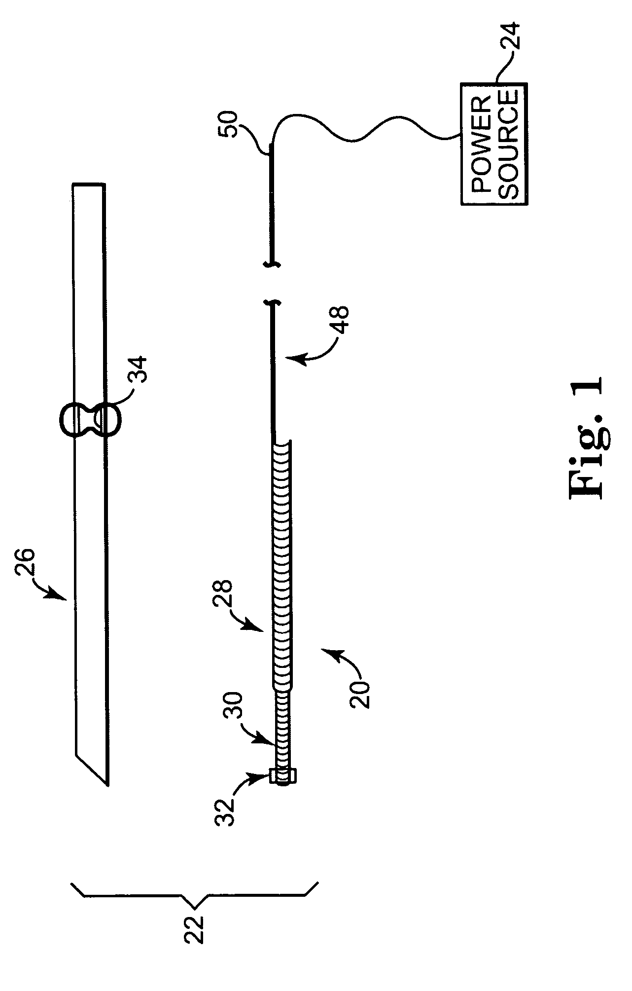
[0026] One embodiment of an implantable medical electrical lead 20 in accordance with principles of the present invention is shown in simplified form in FIG. 1 as part of a system 22 for delivering stimulation energy to bodily tissue of a patient (not shown) via a power source 24 (e.g., a pulse generator) maintained external the patient. The system 22 can incorporate components in addition to those illustrated, and includes the lead 20 and a needle 26. The lead 20 includes a flexible lead body 28, otherwise forming an electrode 30, and a fixation assembly 32 (shown schematically). Details on the various components are provided below. In general terms, however, the lead 20 is sized to be slidably received within a small diameter lumen 34 (referenced generally) of the needle 26 for percutaneous delivery to a stimulation site. The fixation assembly 32 defines a contracted state when disposed within the needle lumen 34, and transitions to an expanded state following deployment from the ...


PUM


Abstract

An implantable medical electrical lead for applying electrical stimulation energy from an external power source and adapted to be introduced through a small diameter needle. The lead includes a lead body and a fixation assembly. The lead body includes a wire and an electrically non-conductive material. The wire forms a wound coil along a distal portion thereof. The non-conductive material covers some of the wire coil, with an uncovered distal region of the wire serving as an electrode. The fixation assembly is coupled to the uncovered distal region and includes at least one fixation member. The fixation assembly is transitionable between a contracted state and an expanded state, with the fixation member extending outwardly relative to the coil to a greater extent in the expanded state. In the expanded state, the fixation assembly serves to inhibit axial migration of the lead body.

Description

BACKGROUND OF THE INVENTION [0001] The present invention relates to systems and methods for providing electrical stimulation to bodily tissue, such as electrically stimulating a portion of a patient's nervous system. More particularly, it relates to temporarily implantable electrical stimulation leads, such as a peripheral nerve evaluation lead used to stimulate a sacral nerve, with enhanced resistance to migration, and related systems and methods of use. [0002] A number of human bodily functions are affected by the nervous system. For example, bodily disorders, such as urinary incontinence, urinary urge / frequency, urinary retention, pelvic pain, bowel dysfunction (constipation, diarrhea, etc.), erectile dysfunction, etc., are all bodily functions influenced by the sacral nerves. As a point of reference, urinary incontinence is the involuntary loss of control over the bladder. Incontinence is primarily treated through pharmaceuticals and surgery. Many pharmaceuticals do not adequate...

Claims


Application Information

Patent Timeline
IPC IPC(8): A61N1/00
CPCA61N1/0558
Inventor BONDE, ERIC H.STETZ, ERIC M.TRONNES, CAROLE A.HENRY, JAMES T.
Owner MEDTRONIC INC
Learn More