Monitoring and controlling an aquatic environment

a technology for monitoring and controlling aquatic environments, applied in pisciculture, aquaria, instruments, etc., can solve the problems of affecting the overall aquatic ecosystem, and difficult to use real-time monitoring and dynamic control of intermediate control devices, so as to achieve efficient and cost-effective aquatic environment, energy-saving environment, and efficient adjustment

Inactive Publication Date: 2007-11-01
BENCHMARK RES TECH
View PDF6 Cites 44 Cited by
  • Summary
  • Abstract
  • Description
  • Claims
  • Application Information

AI Technical Summary

Benefits of technology

[0016]In accordance with further embodiments of the invention, the system provides efficient adjustment of environment parameters to compensate for the dynamic conditions of the aquatic environment. Based on the improved and extensive measurements of the sensor data for the system analysis, the invention may adjust the individual aqua system components to maintain an energy efficient environment.
[0017]In yet another embodiment of the invention, the system may efficiently adjust the aqua system parameters to compensate for any likely system anomaly based on the real-time system anomaly analysis and the predictive failure diagnostics. Such novel preventive measures enable the system to be ready to adjust and quickly adjust, in the event of a likely failure of the potential control device, to maintain an efficient and cost effective aquatic environment.
[0018]In accordance with yet another embodiment of the invention, the monitoring and control system presents information on the aquatic environment's status and performance at a local or a remote location. This information may be presented in user-friendly format. In a specific embodiment, the capabilit

Problems solved by technology

While such traditional monitoring systems are adequate for certain aqua system applications, monitoring, control and system analysis of intermediate control devices, coupled with prompt alert and response to the alert, can be difficult due to factors such as cost of sensors for intermediate control devices, location of the service personnel, response of the service personnel and the nature of the reported problem.
Another shortcoming of such traditional systems is that it is often difficult to use real-time monitoring and dynamic control of the intermediate control devices because, outside a limited range of operating conditions, the intermediate device itself may contrib

Method used


Image

  • Monitoring and controlling an aquatic environment
  • Monitoring and controlling an aquatic environment
  • Monitoring and controlling an aquatic environment

Examples


example 1

[0043]Monitoring the Chiller

[0044]In one example, sensors on the chiller and the chiller motor enable the system to monitor the performance of the chiller. Here the sensors can monitor parameters of the chiller, such as, the chiller operating temperature, the temperature of the chiller coil, the current used by the chiller, the vibration of the chiller, and the flow rate of water coming out of the chiller pump. If the system, using the sensor fusion technology, detects a failure or an impending failure based on a comparison of the recorded parameter with the reference and / or threshold parameter, the system can send an alert and take measures to minimize the aqua system temperature changes. Such measures may include regulating the lights to reduce the addition of heat while waiting for repair or maintenance. The monitoring scheme described above, although specifically described in relation to a chiller, is not limited to the chiller. A person of ordinary skill in the art will recogni...

example 2

[0048]A Cost Effective Method of Using Temperature Sensors, Instead of Flow Rate Sensors, to Assess the Circulation in an Aquatic Environment

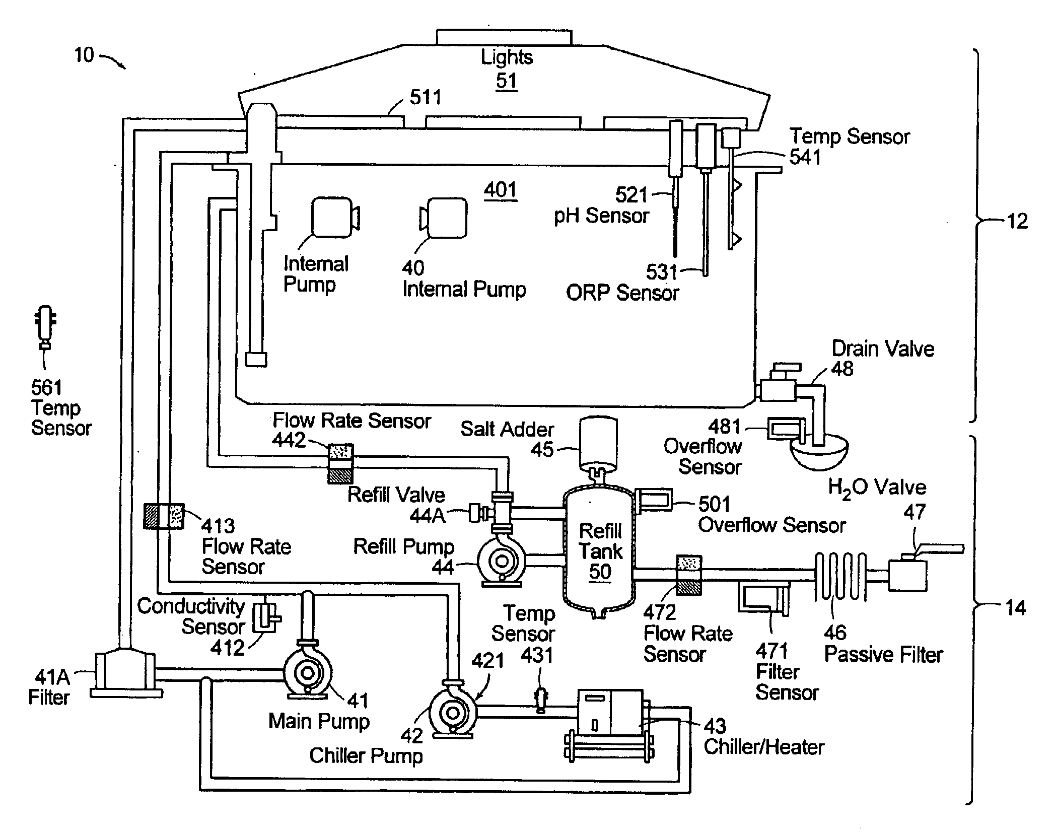
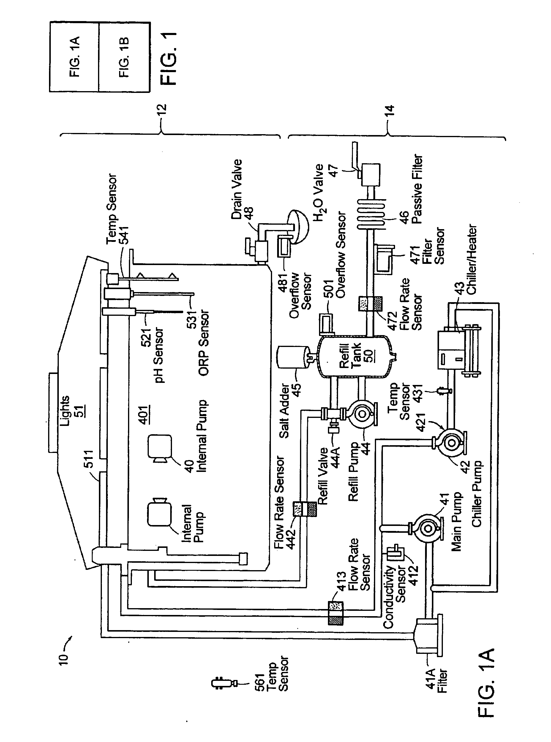
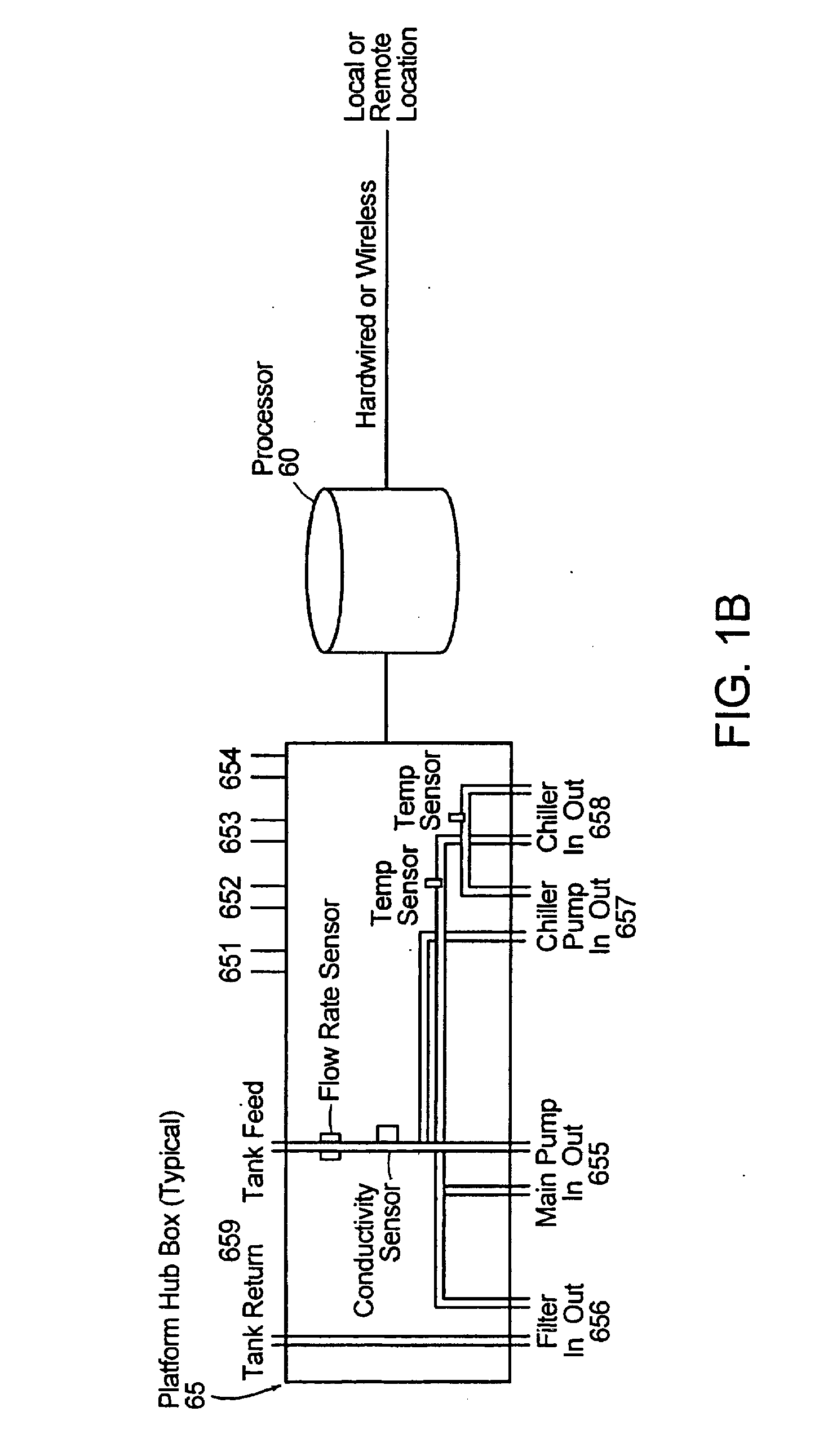
[0049]In this example, as illustrated in FIG. 2, a semi-industrial size aquarium 10 has a sophisticated aquarium control system. The control system uses a variety of sensors and actuators connected to a centralized or computer control system such as processor 60 to regulate the aquatic environment (heat, cooling, lighting, etc.) in a way that seeks to maximize ecosystem stability. A primary failure mode of the ecosystem is loss of water circulation through a chiller resulting in a rise in the temperature of the aquarium. The loss can be catastrophic, as in a pump motor failure, or can be gradual as in the slow clogging on an inline filter. In either case, when the lack of circulation reaches a critical state, it can be detected through a rise in the aquarium water temperature. Here, the control system may use a flow rate sensor 413 to detect bo...

example 3

[0061]Predicting an Anomaly in the System and Sending an Alert

[0062]This example shows how the invention may predict an anomaly in an aqua system and. subsequently send out notification. FIG. 6 is a graphical representation of a typical temperature performance profile from an aqua system 100 shown in FIG. 5. Other profiles may be based on other parameters or a combination of parameters of the system. This embodiment of the aqua system includes a sump tank, the prerequisites components, such as pumps, filters, chillers, heaters etc., and associated sensors, such as temperature sensors, level sensors, flow rate sensors etc., for maintaining the aquatic environment.

[0063]Referring back to the graph of FIG. 6, the nominal tank temperature profile shows the temperature of the water in the tank. The nominal sump temperature shows the temperature of the water in the sump tank. Ideally and based on the circulation path in the aquatic environment, the sump temperature should track the tank t...


PUM


Abstract

A system and method for monitoring and controlling an aquatic environment thus regulating the aquatic environment and maximizing the stability of the aquatic ecosystem. This system uses sensor and data fusion algorithms to perform system anomaly analysis and predictive failure diagnostics based on the output of sensors associated with the aquatic environment control devices. Based on the system anomaly analysis and/or predictive failure diagnostics, the system may continuously adjust the system parameters to maintain an efficient and stable aquatic environment, alert local or remote monitors of failed or impending failure of control devices. In addition, the system may present the system anomaly analysis and predictive failure diagnostics information at a local or remote location to enable the monitor to address any problems presented in situ.

Description

CROSS REFERENCE TO RELATED APPLICATION[0001]This application claims priority from and incorporates herein by reference, U.S. Provisional Application Ser. No. 60 / 746,013, filed Apr. 28, 2006, with the United States Patent and Trademark Office.TECHNICAL FIELD[0002]The present invention relates to apparatus, processes and systems for monitoring and controlling aquatic environments including analyzing and predicting an anomaly in an aquatic environment.BACKGROUND[0003]Aquariums or aqua systems have been maintained since antiquity. These aqua systems range from the professional and industrial types used in places like the New England Aquarium, to mid-size ones in professional buildings, restaurants, pet shops or homes, to the small bookshelf ones in most children's rooms. Generally, most aqua systems have two components: an enclosure housing the organism(s) or inhabitants of the aqua system and the machinery maintaining the enclosure environment. The enclosure can be simple or sophistica...

Claims


Application Information

Patent Timeline
IPC IPC(8): G05B11/01
CPCG05B23/0235A01K63/003
Inventor KINSEY, E. WAYNE
Owner BENCHMARK RES TECH
Why Eureka
Try Eureka