Vibration control of free piston machines through frequency adjustment

a free piston machine and frequency adjustment technology, applied in the direction of piston pumps, pump parameters, domestic cooling apparatus, etc., can solve the problems of unconfined by conventional crankshafts and connecting rods, reciprocating machines cause substantial vibration, and vibration is ordinarily undesirable, so as to reduce or minimize the amplitude of mechanical vibration of mechanical apparatus

Inactive Publication Date: 2007-11-08
SUNPOWER
View PDF14 Cites 66 Cited by
  • Summary
  • Abstract
  • Description
  • Claims
  • Application Information

AI Technical Summary

Benefits of technology

[0020] The invention is a method and apparatus for minimizing the amplitude of mechanical vibrations of a mechanical apparatus that includes a linear motor coupled to and driving a reciprocating mass of a driven machine in reciprocation at a driving frequency. The coupled motor and driven machine have one or more springs applying a force upon the composite reciprocating mass to form a resonant main system having a main system resonant frequency of reciprocation. A driving frequency range over which the driven machine operates at an acceptable efficiency of operation is determined and stored. A parameter of the operation of the mechanical apparatus is sensed and the linear motor is driven in response to the sensed parameter at a driving frequency that is offset from the main system resonant frequency of reciprocation, is within the driving frequency range of acceptable efficiency of operation and reduces or minimizes the amplitude of mechanical vibration of the mechanical apparatus under existing operating conditions.

Problems solved by technology

Linear, freely reciprocating machines reciprocate with a controllable stroke and are unconfined by conventional crankshafts and connecting rods.
However, linear, freely reciprocating machines cause substantial vibration because they have one or more masses that are linearly reciprocating within a common housing and / or are attached to a common support frame.
This vibration is ordinarily undesirable and a variety of systems have been developed to minimize the amplitude of such vibrations.
The vibration problem can be further complicated if a mechanical apparatus consists of a main machine or system, comprising a prime mover driving a driven machine, that is also coupled to other equipment that includes one or more secondary vibrating systems.
If the resonant frequency of the parasitic resonant system is sufficiently near the driving frequency of the main machine, the parasitic resonant system may vibrate at an excessive amplitude.
If the parasitic resonant system vibrates at the drive frequency and at less than 90° out of phase with the main system, it can increase the total vibration of the mechanical apparatus.
Although these systems perform satisfactorily under relatively stable operating conditions, under extreme variations in operating conditions they can encounter difficulties.
Therefore, a relatively small variation in the natural frequency of the vibration balancer results in a large variation in its effective amplitude of oscillation if the driving frequency remains the same.
Consequently the ability of the vibration balancer to cancel the vibrations of the vibrating main machine is substantially diminished.
Temperature can also change the dynamic behavior of a Stirling engine resulting in a shift of its operating frequency.
As a result, a mechanical apparatus with a vibration balancer can be well balanced and exhibit an acceptable amplitude of vibration under some operating conditions, but if the operating conditions depart sufficiently from the preset operating conditions, the vibration balancer will become less effective because the change in operating conditions changes the resonant or natural frequency of the vibration balancer or changes it phase relation to the main system or both.
If the vibration balancer becomes less effective, the amplitude of the vibrations increases.
As a result, a secondary system that does not aggravate the vibration of the mechanical apparatus under some operating conditions can become a problem when the operating conditions change sufficiently.
A component of a mechanical apparatus that was not a vibration problem can become a problem when operating conditions change sufficiently.
Although it is possible to construct a vibration balancer that would be able to vary its spring constant or otherwise vary its natural frequency of oscillation, such a vibration balancer would be even more expensive than conventional vibration balancers.
Vibration balancers are not only a considerable cost, they also take up space and add weight to a product.

Method used


Image

  • Vibration control of free piston machines through frequency adjustment
  • Vibration control of free piston machines through frequency adjustment
  • Vibration control of free piston machines through frequency adjustment

Examples


Embodiment Construction

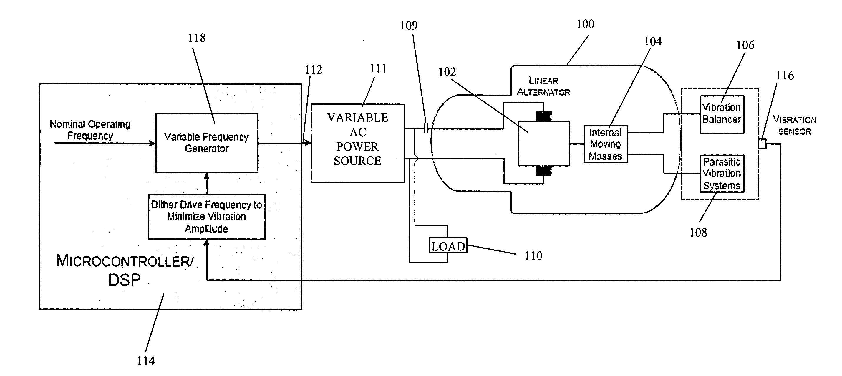
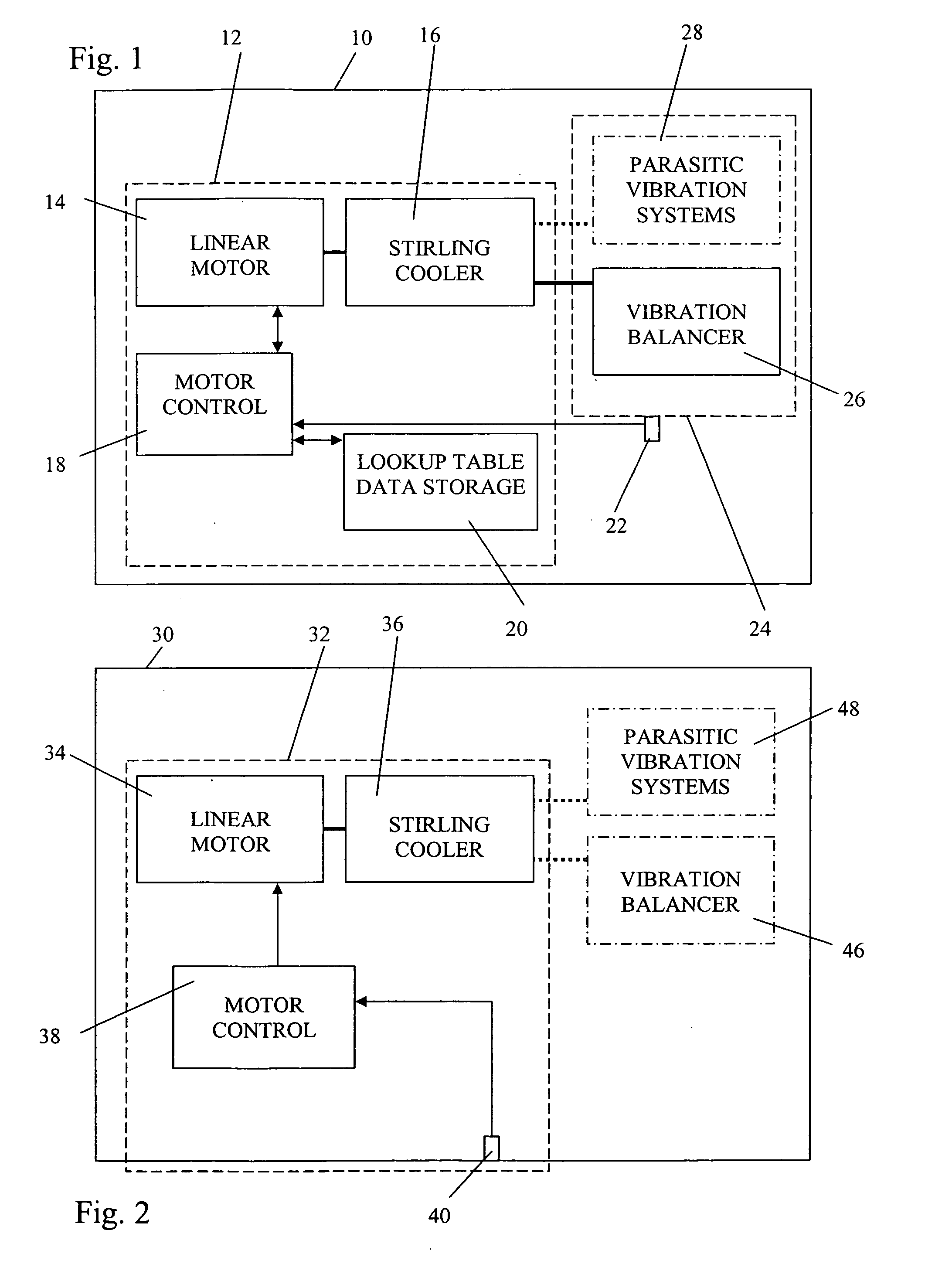
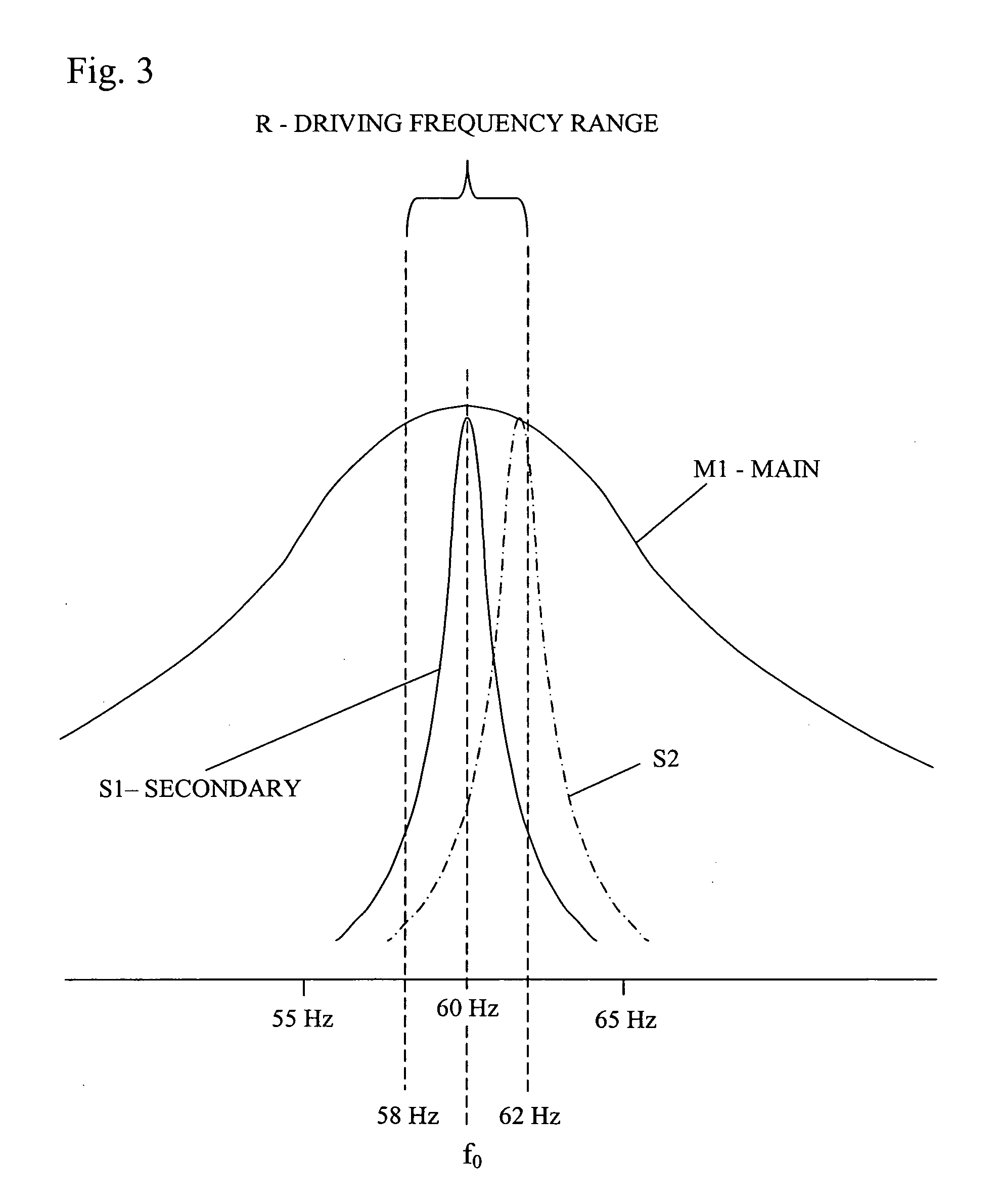
[0027] The invention makes use of the observation that, for a mechanical apparatus that includes a vibrating or reciprocating main machine coupled to a secondary vibrating system, which can include a vibration balancer, there are three frequencies that are important. There are the resonant (or natural) frequency of the vibrating main machine, the resonant (or natural) frequency of the secondary vibrating system and the operating frequency of the main machine. The operating frequency of the main machine is also the operating frequency of the vibration balancer and any other secondary vibrating system coupled to the main machine.

[0028] If a graph is made of frequency vs. amplitude of vibration for any resonant system, the plotted amplitudes form a resonant peak centered at a resonant frequency. These peaks can rise and fall in a range extending from a broad, gradual manner, to a sharp, steep manner. The sharper the peak, the higher the quality factor “Q” of the resonant system, as kn...


PUM


Abstract

A method and apparatus for minimizing the amplitude of mechanical vibrations of a mechanical apparatus including a linear, freely reciprocating, prime mover coupled to and driving a reciprocating mass of a driven machine in reciprocation at a driving frequency. The coupled prime mover and driven machine have a spring applying a force upon the reciprocating mass to form a resonant main system having a main system resonant frequency of reciprocation. A driving frequency range over which the driven machine operates at an acceptable efficiency of operation is determined and stored. A parameter of the operation of the mechanical apparatus, such as the amplitude of vibrations or an operating temperature, is sensed and the prime mover is driven in response to the sensed parameter at a driving frequency that is offset from the main system resonant frequency of reciprocation, is within the driving frequency range of acceptable efficiency of operation and reduces or minimizes the amplitude of mechanical vibration of the mechanical apparatus under existing operating conditions.

Description

BACKGROUND OF THE INVENTION [0001] 1. Field of the Invention [0002] This invention relates generally to minimizing mechanical vibrations of a mechanical apparatus that includes one or more masses driven in reciprocation by a linear, freely reciprocating, prime mover and using the electronic controller that controls that prime mover. [0003] 2. Description of The Related Art [0004] Linear, freely reciprocating machines are often used because they provide improved durability, reduced wear, controllability and efficiency. Freely reciprocating machines include linear compressors, free piston Stirling engines, Stirling cooler, cryocoolers and heat pumps, linear motors and linear alternators. Linear, freely reciprocating machines reciprocate with a controllable stroke and are unconfined by conventional crankshafts and connecting rods. However, linear, freely reciprocating machines cause substantial vibration because they have one or more masses that are linearly reciprocating within a comm...

Claims


Application Information

Patent Timeline
Patent Type & Authority Applications(United States)
IPC IPC(8): F25B9/00F25D19/00
CPCF04B35/045F04B2201/0806F04B2203/0404F16F15/02H02P25/027F25B2309/001H02K11/0015H02K11/0073F16F15/22H02K11/21H02K11/33H02P25/032F16F7/10F16F15/00
Inventor UNGER, REUVEN Z-MKEITER, DOUGLAS E.
Owner SUNPOWER
Why Eureka
Try Eureka