Fuel economizer

a fuel economizer and fuel technology, applied in the direction of machines/engines, combustion air/fuel air treatment, charge feed systems, etc., can solve the problems of high cost and difficulty in mounting and disassembly, shortened life of engines, and high maintenance and cleaning costs, so as to reduce waste gas produced

Active Publication Date: 2007-11-08
WANG JIN LANG
View PDF10 Cites 11 Cited by
  • Summary
  • Abstract
  • Description
  • Claims
  • Application Information

AI Technical Summary

Benefits of technology

[0007]It is one objective of the present invention to provide a fuel economizer, in which a plurality of thermal conductive elements provided with a pipeline of the fuel economizer absorbs a large quantity of heat from the outside of the fuel economizer to

Problems solved by technology

However, the disadvantages of the conventional fuel saver lie in that the product has a rather complicated structure, which results in a high cost and difficulty in mounting and disassembling and, therefore, very expensive maintenance and clean so that i

Method used


Image

  • Fuel economizer
  • Fuel economizer
  • Fuel economizer

Examples


first embodiment

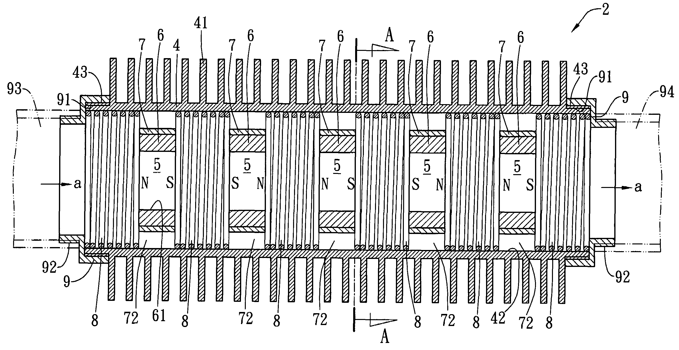
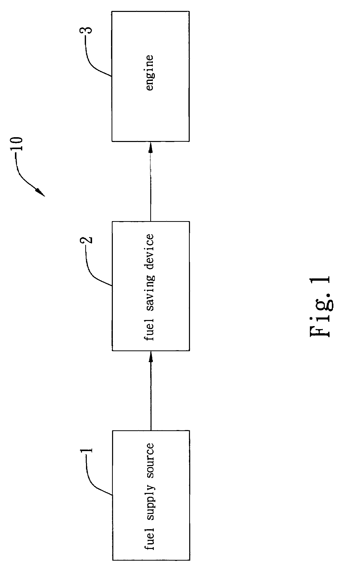
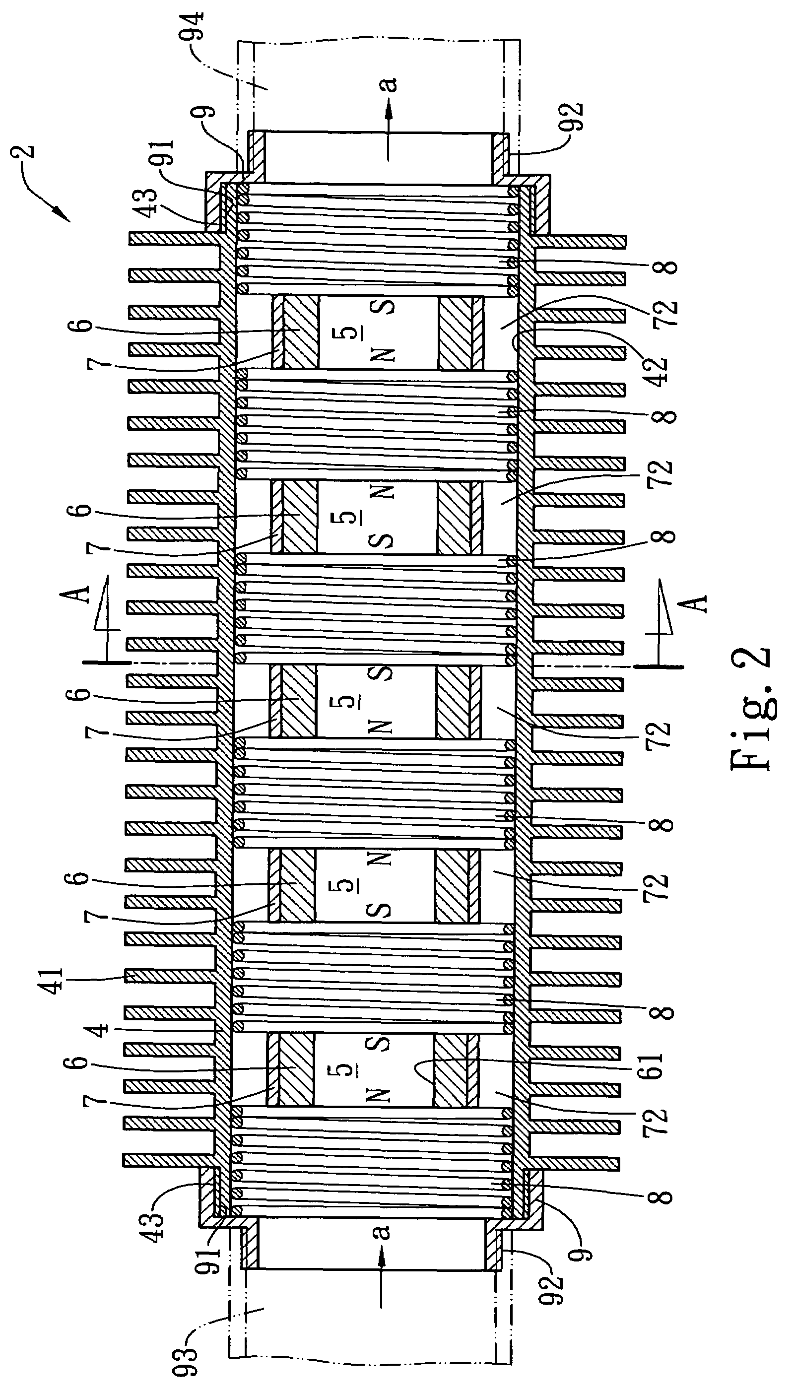
[0025]Referring to FIG. 1, which shows a block diagram of a fuel system associated with the fuel economizer of the present invention. In this preferred embodiment, a fuel system 10 comprises at least a fuel supply source 1, an engine 3, and a fuel economizer 2 provided between the fuel supply source 1 and the engine 3. The fuel economizer 2 does not require electric power and has a simple structure in which the components can be disassembled easily for clean or maintenance, and has an affordable price to meet the market acceptance. Please also refer to FIG. 2, which shows a cross sectional view of the fuel economizer according to the present invention. The fuel economizer 2 is used for transporting the fuel supplied from the fuel supply source 1 to the engine 3 for combustion. A pipeline 4 has fins 41 thereof for preheating the fuel flowing through a chamber 5 thereof so that the temperature of the fuel can be increased beforehand and the fuel having been in the engine 3 can reach e...

second embodiment

[0029]Referring to FIG. 4, which shows a cross sectional view of the fuel economizer according to the present invention, in which the thermal conducting elements of the fuel economizer 21 are coils 411 made of thermal conductive material. The coils 411 can be hollow or solid and functioned as having the surface areas thereof used for absorbing a large quantity of heat from the outside of the fuel economizer 21, and conducting the heat to the inner surface 42 of the pipeline 4 so as to preheat the fuel flowing through the spacings 72. As such, the temperature of the fuel can be increased beforehand to reach an ignition point for facilitating ignition and complete combustion, and thus reducing waste gas (carbon deposit) produced.

[0030]The fuel economizer of the present invention has advantages as follows. It does not require power supply and has a simple structure easy to clean and maintain and has an affordable price. The pipeline can provide preheating function for the fuel flowing ...


PUM


Abstract

A fuel economizer comprises a pipeline with thermal conducting elements and having a chamber contained therein, a plurality of magnetic elements each of which having a through hole formed therein and wrapped within a metal element that is formed with a plurality of spacings and disposed within the chamber of the pipeline, and a plurality of elastic elements disposed within the chamber of the pipeline and located at two opposite sides of the magnetic elements, respectively.

Description

BACKGROUND OF THE INVENTION[0001]1. Field of the Invention[0002]The present invention relates to a fuel economizer and, more particularly to a fuel economizer that does not require electrical power and has a simple structure easy to clean and maintain and also has an affordable price.[0003]2. Descriptions of the Related Art[0004]Under the trend towards energy saving and environmental protection, typically a fuel saver may be mounted where the fuel has not yet entered the engine of a car so as to increase the horsepower and reduce the carbon deposit and save the fuel as well.[0005]The conventional fuel saver has a structure that can release far-infrared ray or magnetic energy, thereby finely activating the fuel molecules transported in the fuel pipes to increase the combustion efficiency and fulfill the purpose for fuel saving.[0006]However, the disadvantages of the conventional fuel saver lie in that the product has a rather complicated structure, which results in a high cost and di...

Claims


Application Information

Patent Timeline
IPC IPC(8): F02M27/00
CPCF02M27/045
Inventor WANG, JIN-LANG
Owner WANG JIN LANG
Why Eureka
Try Eureka