Transverse tab application method and apparatus

a technology of tape tabs and application methods, applied in the field of transverse tab application methods and apparatuses, can solve the problem of almost unnoticeable cutting noise levels, and achieve the effects of reducing the coefficient of friction between the bump transfer surface and the traveling web, and reducing the level of vacuum

Active Publication Date: 2007-11-08
CURT G JOA
View PDF99 Cites 17 Cited by
  • Summary
  • Abstract
  • Description
  • Claims
  • Application Information

AI Technical Summary

Benefits of technology

[0012] The present invention may include a vacuum commutation system configured to remove or reduce the level of vacuum used to hold each tab to the anvil surface just before the point of transfer. The materials and finishes selected for the anvil and the bump transfer surfaces provide a situation in which the coefficient of friction between the bump transfer surfaces and the traveling web is relatively high, while the coefficient of friction between the tape tab and the anvil is relatively low. The highly aggressive nature of the bond between the adhesive side of the tape tab and the target surface of the traveling web ensures that there i

Problems solved by technology

In fact, the underlying noise of the mechanical drive systems and the travelin

Method used


Image

  • Transverse tab application method and apparatus
  • Transverse tab application method and apparatus
  • Transverse tab application method and apparatus

Examples


embodiment 209

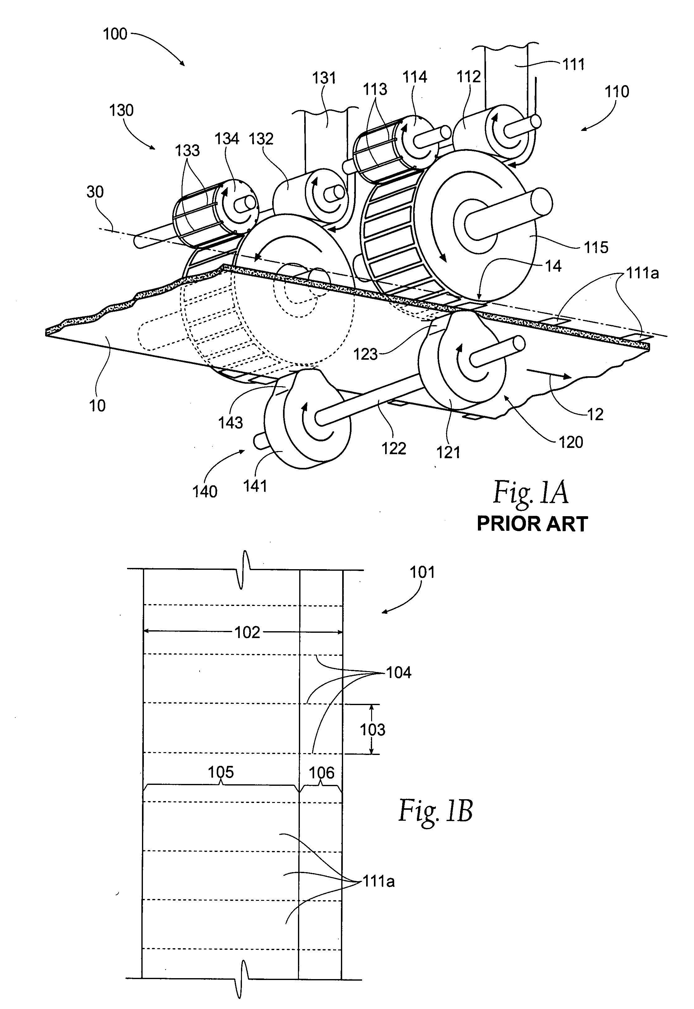
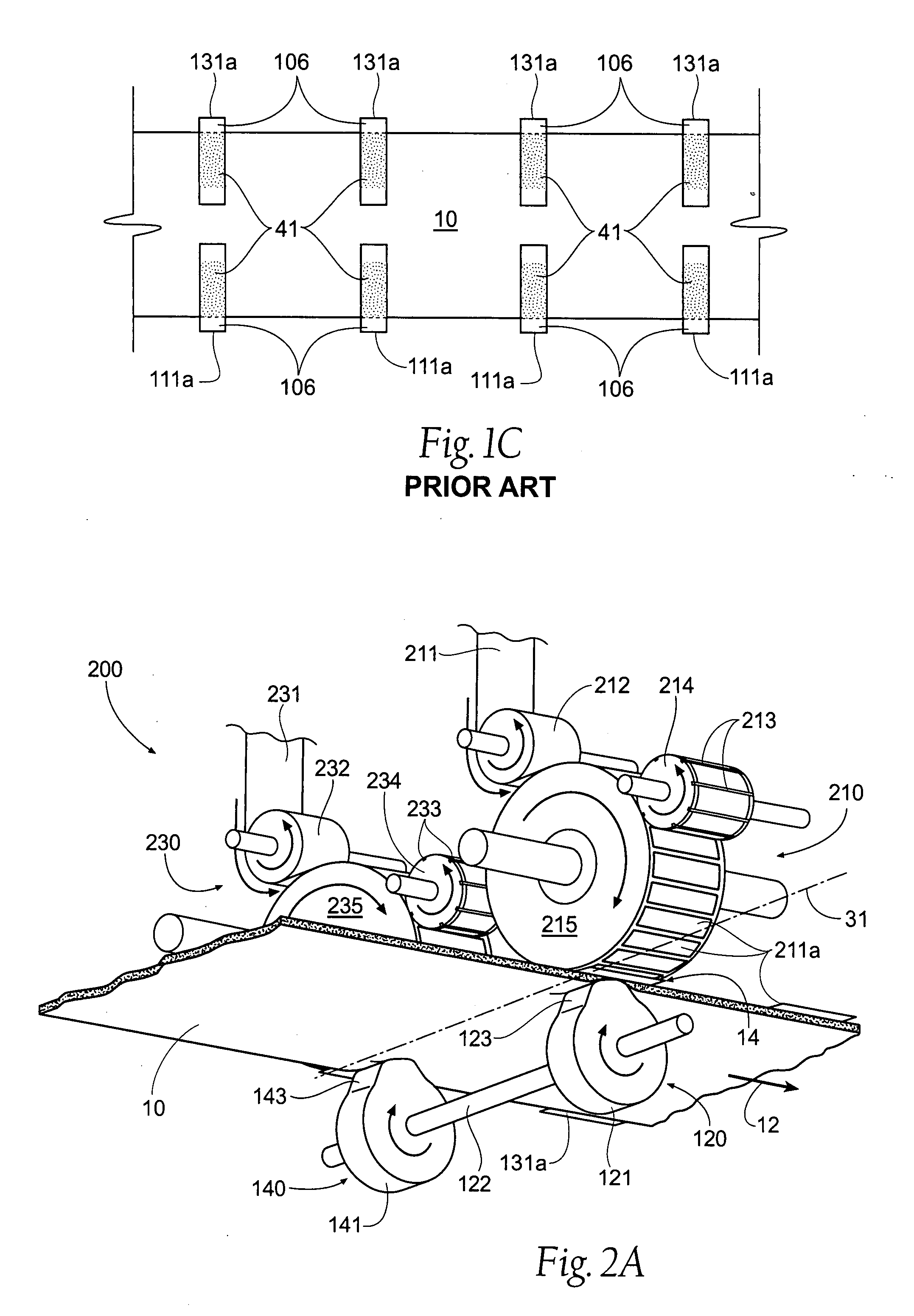
[0040]FIG. 3B is an overhead view of a web 10 having tabs 211a placed by the embodiment 209 of the apparatus and method of the present invention. As can be seen, the use of a modified tab applicator 220 provides a plurality of attachment sites 43 spaced at predetermined locations along the tab 211a, thereby improving adhesion between the tab 211a and the web 10.

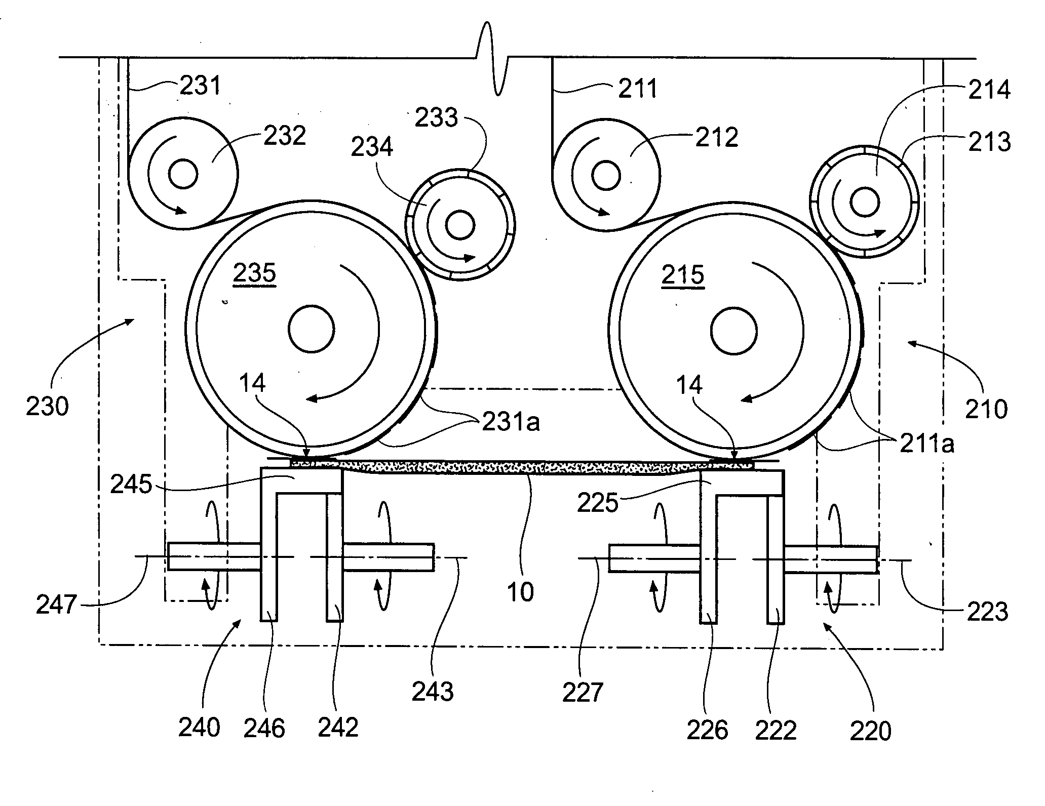
[0041]FIG. 4 shows a front elevation view of the apparatus of FIG. 3A. The incoming web 211 is fed about a roller 212. The web 211 travels further to contact the anvil 215. The web 211 is fed to the anvil 215 at a speed that approximately equals the speed at which the outer periphery of the anvil 215 is traveling. If desired, the anvil 215 may rotate at a slightly higher speed than the linear speed of the web 211. The blades 213 of the rotary cutter 214 are also traveling at a peripheral speed substantially equal to that of the anvil 215. After being cut, the tabs 211a are carried on the outer surface of the anvil 211a. The t...

embodiment 309

[0045]FIG. 5C shows an overhead view of a web of material 10 having tabs 311a applied to the web 10 by the embodiment 309 of FIG. 5A. As can be seen, the use of a modified tab applicator 320 provides a plurality of attachment sites 44 spaced at predetermined locations about the tab 311a, thereby improving adhesion between the tab 311a and the web 10.

[0046] As shown in FIG. 3A, FIG. 4, and FIG. 5A, the axes of rotation of the tab applicators 220,240 may be generally perpendicular skew from the axes of rotation of the anvils; however, the invention also contemplates tabs placed onto a web at a predetermined oblique skew angle. FIG. 6 represents a diagrammatic view of such an arrangement. The tabs 12 are provided to the transfer location 14 in an oblique skew manner and placed onto the web of material 10 at a desired angle, such as approximately a 45 degree angle. Therefore, the relative angle between the anvil surface tangent and the web 10 may lie at any skew angle, perpendicular or ...


PUM

PropertyMeasurementUnit
Adhesivityaaaaaaaaaa
Distanceaaaaaaaaaa

Abstract

A method and apparatus for applying tabs to a traveling web of material at a transfer position when the tabs are provided to the transfer position in a path that is skew to the web travel path. A tab supply assembly carries the tabs in a tab path that is either perpendicularly skew or obliquely skew to the travel path of the web. The web is generally spaced from the tab supply assembly. A plurality of bump transfer surfaces is adapted to urge the web towards the tab supply assembly, thereby contacting a tab.

Description

RELATED APPLICATION [0001] This application is a continuation-in-part application of co-pending U.S. patent application Ser. No. 11 / 371,468, filed 9 Mar. 2006, and entitled “Transverse Tape Application Method and Apparatus,” which claims the benefit of U.S. Provisional Patent Application Ser. No. 60 / 659,785, filed 9 Mar. 2005, and entitled “Transverse Tape Application Method and Apparatus.”BACKGROUND OF THE INVENTION [0002] The present invention relates to processes and apparatus for applying tabs to traveling webs, and more specifically to a method and apparatus for applying tabs to a traveling web of material at a transfer position when the tabs are provided to the transfer position in a path that can be skew to the travel direction of the web of material. The invention has particular applicability to the manufacture of disposable diapers. [0003] The history of cutting and applying tabs to disposable diaper webs is now entering its fourth decade. Over the course of that time, vari...

Claims


Application Information

Patent Timeline
IPC IPC(8): B29C65/00
CPCA61F13/15756B65H39/14B65H2301/324Y10T156/133B65H2801/57Y10T156/178B65H2601/521B65H2408/2171
Inventor ANDREWS, ROBERT E.
Owner CURT G JOA
Why Eureka
Try Eureka