
High efficiency liquid crystal display projection system

Inactive Publication Date: 2007-11-08
IND TECH RES INST
View PDF5 Cites 7 Cited by
  • Summary
  • Abstract
  • Description
  • Claims
  • Application Information

AI Technical Summary

Benefits of technology

[0015] The present invention provides a liquid crystal proj

Problems solved by technology

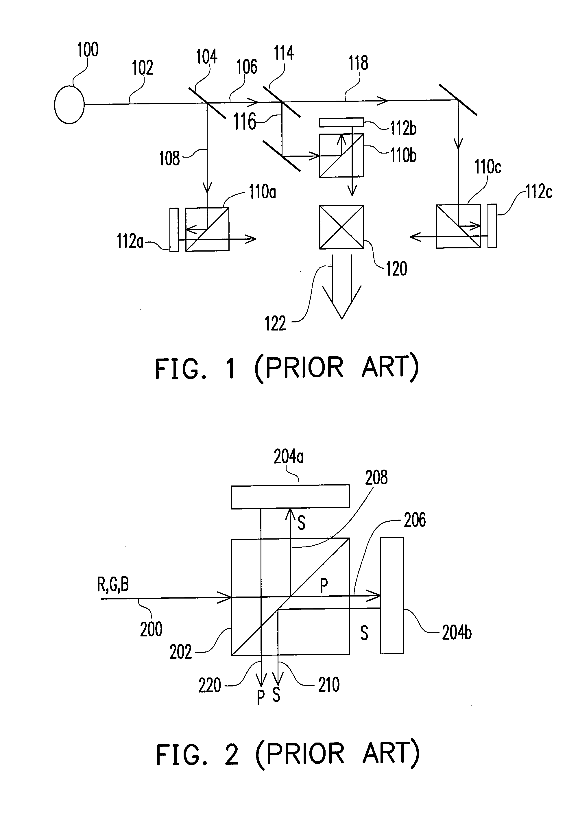
This type of liquid crystal display projection system processes the three primary colors, (red / green / blue, R / G / B), respectively, hence, it is bigger in volume with a higher manufacturing cost and a poorer utility efficiency of lights.
Furthermore, the light-emitting surface of the traditionally used light source gives off uneven brightness.

Method used


Image

  • High efficiency liquid crystal display projection system
  • High efficiency liquid crystal display projection system
  • High efficiency liquid crystal display projection system

Examples


Embodiment Construction

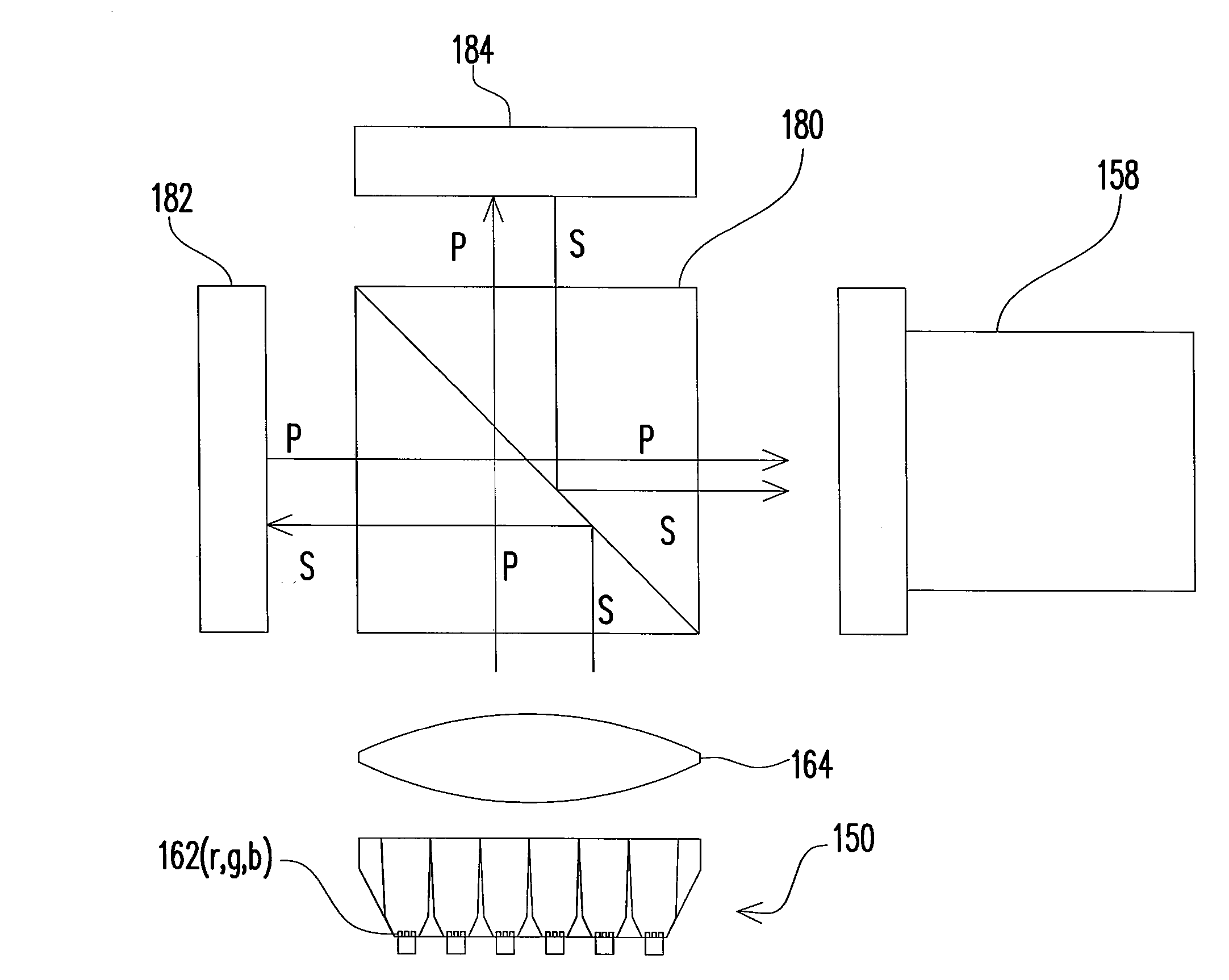
[0028] First, the present invention provides an improved and innovative design of the light source used in the liquid crystal display projection system, which comprises a more uniform planar light source that allows better utility efficiency of lights and provides a more uniform image brightness. It will be illustrated through the following embodiments, and the present invention is not limited to the recited embodiments.

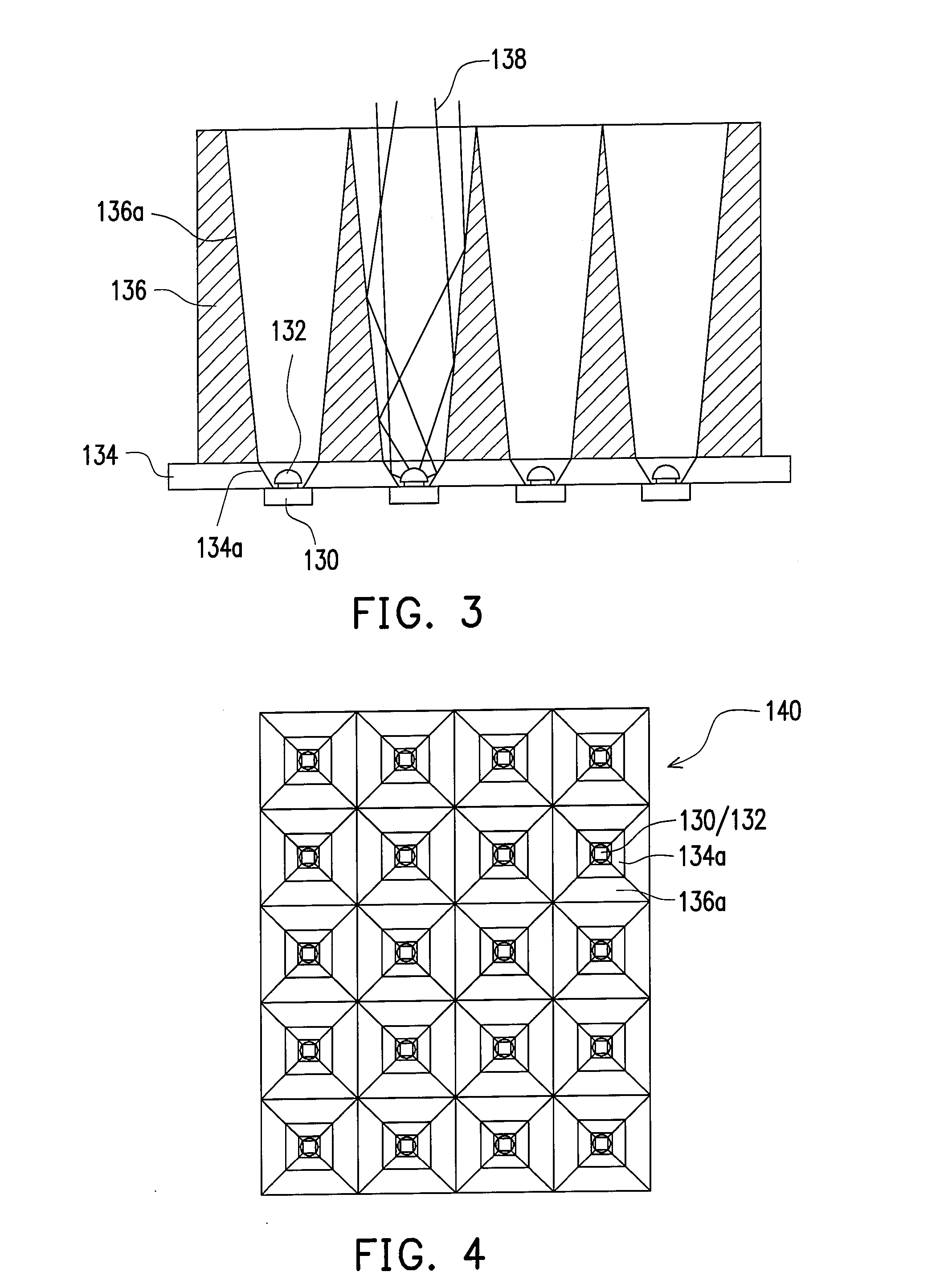
[0029]FIG. 3 is a cross-sectional view, schematically illustrating a structure of an illuminating light source, according to an embodiment of the present invention. FIG. 4 is a top view, schematically illustrating a top view of the structure of the light source corresponding to FIG. 3. In FIG. 3 and FIG. 4, the array of the illuminating light source can include, for example, four illuminating units on one side. An illuminating unit includes a point-like light emitting device, such as an LED having a substrate electrode part 130 and a packaged light emitting part 132...


PUM


Abstract

A transmitting-type liquid crystal display projection system including a planar light source which emits planar white beam or planar R / G / B beams in succession is provided. A first polarization filter receives the planar light source and polarizes the same to be in a first polarization state. A liquid-crystal light valve receives the polarized planar light source, and converts the first polarization state to a second polarization state having a corresponding gray level. A second polarization filter receives a light output from the liquid crystal light valve to produce a second polarization light beam. A projection unit projects the second polarization light beam onto a display plane. Using the same planar light source, a polarization beam splitting (PBS) device with a refection-type liquid crystal light valve can be used to achieve the reflection-type projection system.

Description

CROSS-REFERENCE TO RELATED APPLICATION [0001] This application is a continuation-in-part of a prior application Ser. No. 11 / 223,557, filed Sep. 9, 2005, and claims the priority benefit of Taiwan application serial no. 95141897, filed on Nov. 13, 2006. The prior application Ser. No. 11 / 223,557 claims the priority benefit of Taiwan application serial no. 94125065, filed on Jul. 25, 2005. The entirety of each of the above-mentioned patent applications is hereby incorporated by reference herein and made a part of this specification.BACKGROUND OF THE INVENTION [0002] 1. Field of the Invention [0003] The present invention relates to a projection display technology, and more particularly, to a high efficiency liquid crystal display projection system. [0004] 2. Description of Related Art [0005] The projection liquid crystal display technology has been a usual technology. The traditional liquid crystal display projection system mainly uses the reflective liquid crystal on silicon (LCOS) pane...

Claims


Application Information

Patent Timeline
IPC IPC(8): G02F1/1335
CPCG02F1/133603G02F2001/133607G02F2001/133622G03B33/08G03B21/2073H04N9/3111H04N9/3155H04N9/3164H04N9/3197G03B33/12G02F1/133607G02F1/133622
Inventor TAIN, RA-MINLIN, CHUN-CHUANHAN, WEI-KUOHU, JE-PINGCHEW, CHEN-HUNG
Owner IND TECH RES INST
Learn More