Conically-shaped glenoid implant with a prosthetic glenoid insert used in total shoulder arthroplasty and method

a glenoid insert and implant technology, applied in the field of prosthetic glenoid components, can solve the problems of unfavorable bone ingrowth and unconducive environment, and achieve the effect of promoting bone ingrowth and large surface area

Inactive Publication Date: 2007-11-08
STCHUR ROBERT P
View PDF11 Cites 37 Cited by
  • Summary
  • Abstract
  • Description
  • Claims
  • Application Information

AI Technical Summary

Benefits of technology

[0010] A further object of the present invention is to provide a conically-shaped glenoid implant and method that promotes bone ingrowth.
[0011] An even further object of the present invention is to provide a conically-shaped glenoid implant and method that has a large surface area for boney ingrowth to occur.
[0012] Another object of the present invention is to provide a conically-shaped glenoid implant and method that can remain in the glenoid for a long length of time.
[0013] The present invention fulfills the above and other objects by providing a conically-shaped glenoid implant having a fastening means for the acceptance of a conventional prosthetic glenoid insert and a hole located thereon for the acceptance of a locking means. The fastening means are preferably notches while the locking means is reverse barbs. An optional cannulated screw or keels may be located on the exterior surface of the cone for additional securement of the conically-shaped glenoid implant and to prevent rotation of the conically-shaped glenoid implant in the glenoid. The conically-shaped glenoid implant is preferably coated and porous so as to perm

Problems solved by technology

However, although the results obtained from undergoing total shoulder arthroplasty are initially positive, the prosthetic polyethylene glenoid insert does not remain in a permanent position due to glenoid fixation, thus necessitating additional surgeries to replace the prosthetic polyethylene glenoid insert.
The glenoi

Method used


Image

  • Conically-shaped glenoid implant with a prosthetic glenoid insert used in total shoulder arthroplasty and method
  • Conically-shaped glenoid implant with a prosthetic glenoid insert used in total shoulder arthroplasty and method
  • Conically-shaped glenoid implant with a prosthetic glenoid insert used in total shoulder arthroplasty and method

Examples


Embodiment Construction

[0032] For purposes of describing the preferred embodiment, the terminology used in reference to the numbered components in the drawings is as follows:

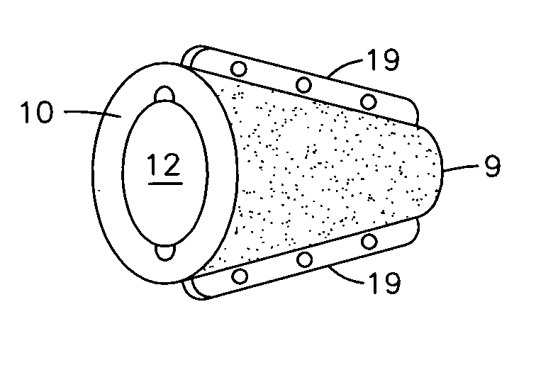
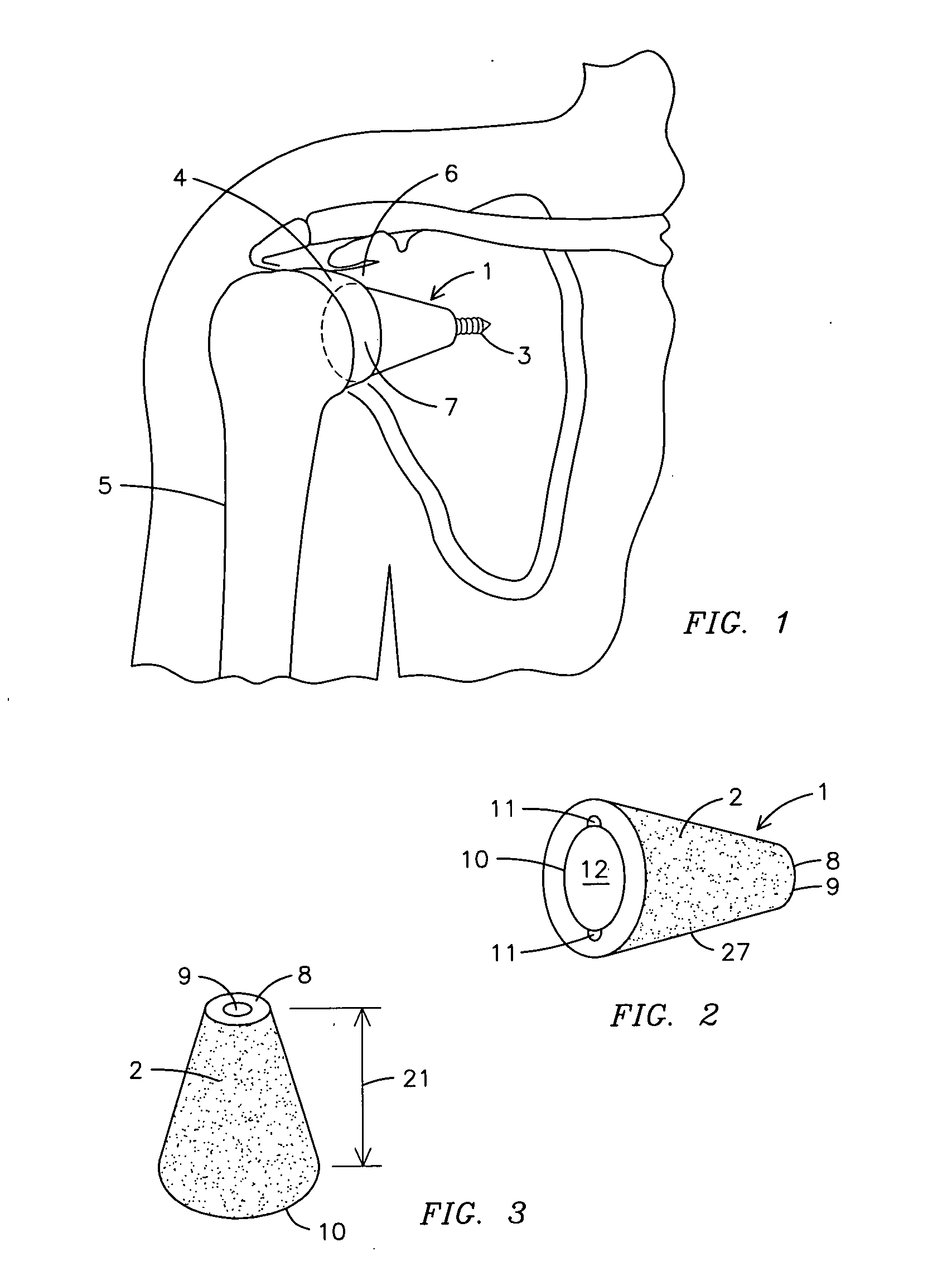
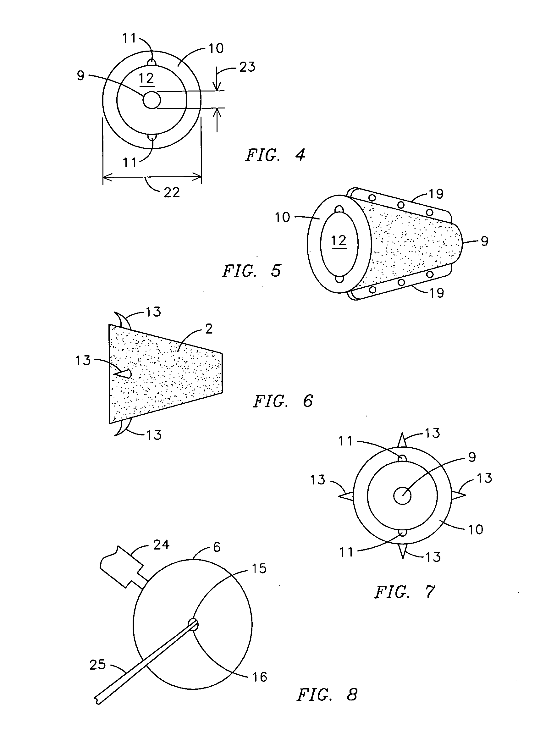
[0033]1. conically-shaped glenoid

[0034]2. cone exterior surface

[0035]3. screw

[0036]4. humeral head

[0037]5. humerus

[0038]6. glenoid

[0039]7. prosthetic glenoid insert

[0040]8. coneapex

[0041]9. hole for fastening means

[0042]10. cone base

[0043]11. notches

[0044]12. cone interior surface

[0045]13. barb

[0046]14. cannulated drill

[0047]15. site for insertion of conically-shaped implant, generally glenoid implant

[0048]16. center of glenoid

[0049]17. reamer

[0050]18. cone punch

[0051]19. keel

[0052]20. cannulated inserter

[0053]21. height of cone

[0054]22. width of cone base

[0055]23. width of cone apex

[0056]24. retractor

[0057]25. central guide wire

[0058]26. deltoid muscle

[0059]27. cone

[0060]28. compressive force

[0061]29. sheer force

[0062] Referring to FIG. 1 and other applicable drawings, currently, the total shoulder arthr...


PUM


Abstract

A conically-shaped glenoid implant (1) having a fastening means for the acceptance of a conventional prosthetic glenoid insert (7) and a hole (9) located thereon for the acceptance of a locking means. The fastening means are preferably notches (11) while the locking means is preferably reverse barbs (13). An optional screw (3) or keels (19) may be located on the exterior surface of the cone (2) for additional securement of the conically-shaped glenoid implant (1) in the glenoid (6) and to prevent rotation of the cone (27). By using the present invention, bone ingrowth is achieved because sheer forces are converted to compressive forces and surface area for ingrowth is significantly increased.

Description

BACKGROUND OF THE INVENTION [0001] This invention relates to prosthetic glenoid components, more particularly, a conically-shaped glenoid implant for holding a prosthetic glenoid insert used in total shoulder arthroplasty wherein the device is conical in shape to provide a larger amount of surface area and to convert sheer force into compressive force. A special tool is also provided to assist in the process. [0002] Arthritis or other injuries to the shoulder typically cause a patient to seek cures for shoulder stiffness and pain. Although not required, total shoulder arthroplasty is often the most effective method for restoring movement and comfort to shoulders damaged by arthritis, injury or other surgeries. [0003] In total shoulder arthroplasty, the surfaces of the humeral head of the humerus (commonly referred to as “the ball”) and the glenoid (commonly referred to as “the socket”) are resurfaced with metal and plastic implants, thereby restoring movement and comfort to the pati...

Claims


Application Information

Patent Timeline
IPC IPC(8): A61F2/40
CPCA61B17/86A61F2/4081A61F2002/30205A61F2002/30331A61F2230/0067A61F2002/30884A61F2002/3092A61F2220/0033A61F2002/30841
Inventor STCHUR, ROBERT P.
Owner STCHUR ROBERT P
Why Eureka
Try Eureka