Magnetic torque-limiting device and method

a torque-limiting device and magnetic technology, applied in the direction of osteosynthesis devices, application, slip coupling, etc., can solve the problems of shock waves along the tool axis and into the fastener, wear and tear may alter the torque setting of the conventional torque-limiting device,

Inactive Publication Date: 2007-11-15
PILLING WECK INC
View PDF4 Cites 286 Cited by
  • Summary
  • Abstract
  • Description
  • Claims
  • Application Information

AI Technical Summary

Benefits of technology

[0012]Yet another embodiment of the present invention relates to a torque-limiting device. The torque-limiting device includes a shaft, first magnetic assembly, housing and second magnetic assembly. The shaft includes a distal end to engage a fastener and a proximal end. The first magnetic assembly is secured to the proximal end. The first magnetic assembly includes a first plurality of magnets. Each one of the first plurality of magnets has a North side adjacent to a South side of another one of the first plurality of magnets. The housing is pivotally secured to the proximal end. The housing includes an outer surface to receive an applied torque. The second magnetic assembly is secured to the housing. The second magnetic assembly includes a second plurality of magnets. Each one of the second plurality of magnets having a North side adjacent to a South side of another one of the second plurality of magnets. Each of the North and South sides of the second magnetic assembly is juxtaposed in attractive cooperative alignment with respective opposite South and North sides, respectively of, the first magnetic assembly to generate an array of attractive magnetic forces between the shaft and the housing.
[0013]Yet another embodiment of the present invention pertains to a torque-limiting device. The torque-limiting device includes a shaft, housing, first magnet, second magnet, first gear, and second gear. The shaft includes a distal end to engage a fastener and a proximal end. The shaft defines an axis of rotation along which a rotation vector is aligned towards the distal end. The housing is pivotally secured to the proximal end. The housing includes an outer surface and an inner surface. The inner surface includes at least a first toothed region having teeth protruding radially inwardly into the housing and at least a second toothed region having teeth protruding radially inwardly into the housing. The first magnet is disposed within the housing. The first magnet is secured to the proximal end. The first magnet includes a first toothed carrier. The second magnet is juxtaposed in attractive cooperative alignment with the first magnet. The second magnet includes a second toothed carrier. The first magnet is aligned with the second magnet with an attractive magnetic force between them. The first gear is pivotally secured to the proximal end. The first gear has teeth to engage the first toothed region and the first toothed carrier. A clockwise external torque applied to the outer surface urges the first toothed region to engage the first gear and clockwise rotate the first gear. The clockwise urging of the first gear urges the first magnet to laterally slide out of alignment with the second magnet. The second gear is pivotally secured to the proximal end. The second gear has teeth to engage the second toothed region and the second toothed carrier. The clockwise external torque applied to the outer surface urges the second toothed region to engage the second gear and clockwise rotate the second gear. The clockwise urging of the second gear urges the second magnet to laterally slide out of alignment with the first magnet and wherein rotation of the housing relative to the shaft is impeded until the first magnet and the second magnet laterally slide past each other by exceeding the attractive magnetic force between them.
[0014]Yet another embodiment of the present invention relates to a torque-limiting device. The torque-limiting device includes a shaft, housing, first magnet, second magnet and lever. The shaft includes a distal end to engage a fastener and a proximal end. The shaft defines an axis of rotation along which a rotation vector is aligned towards the distal end. The housing is pivotally secured to the proximal end. The housing includes an outer surface and an inner surface. The inner surface includes at least one lug protruding radially inwardly into the housing. The first magnet is disposed within the housing. The first magnet is secured to the proximal end. The second magnet is slidably secured to the proximal end and juxtaposed in attractive cooperative alignment with the first magnet. The second magnet includes a magnet bearing surface. The first magnet is urg

Problems solved by technology

In addition, the fastener may include a predetermined amount of torque that has been determined to fatigue or break the fastener.
Unfortunately, as components within these conventional torque-limiting devices slide by one another, wear may alter the torque setting of the conventional tor

Method used


Image

  • Magnetic torque-limiting device and method
  • Magnetic torque-limiting device and method
  • Magnetic torque-limiting device and method

Examples


Embodiment Construction

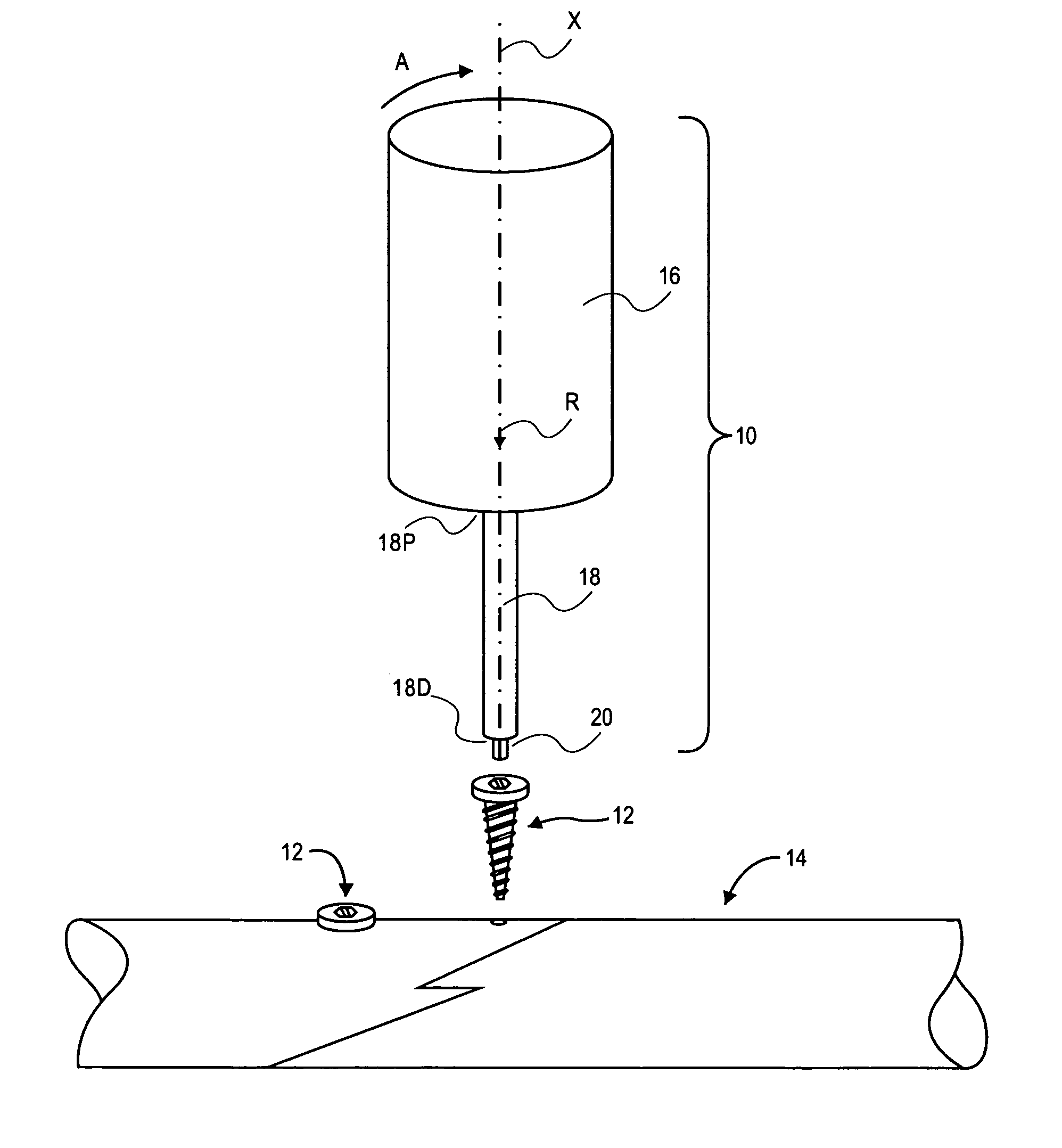
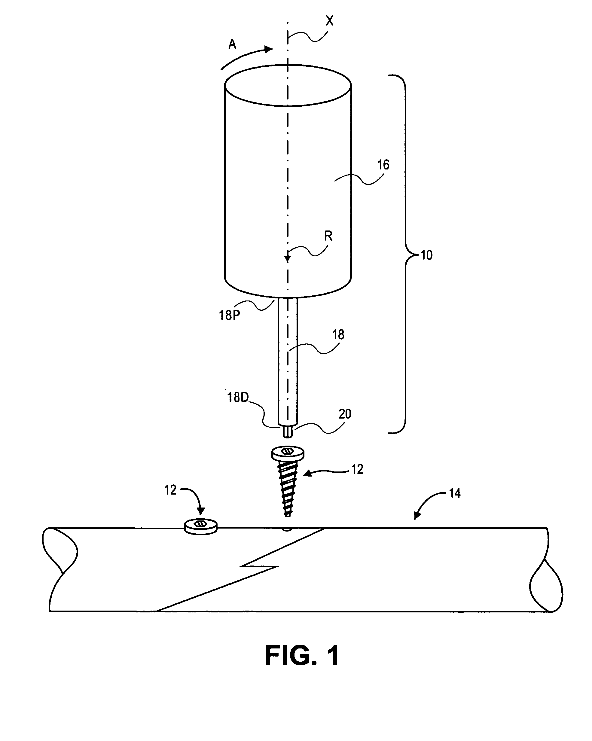
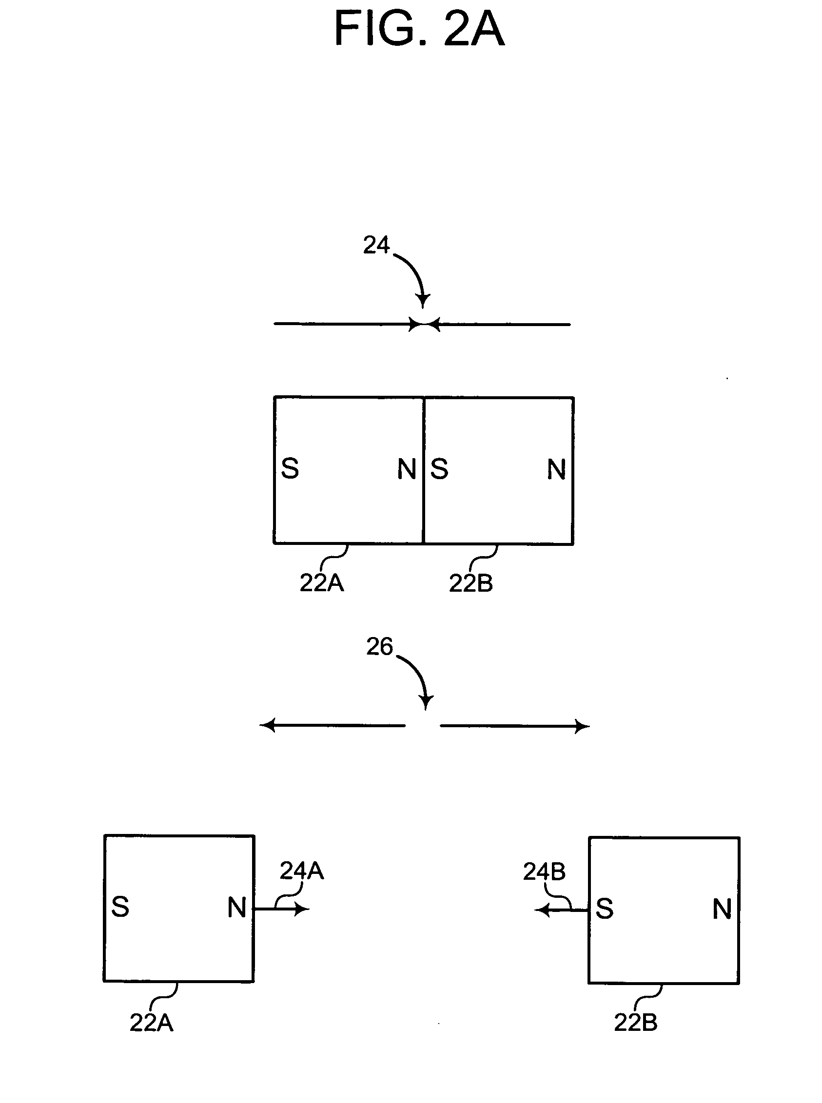
[0045]The present invention provides a magnetic torque-limiting device and method. A detailed description of the magnetic method utilized in the preferred embodiment will clarify the understanding of the phenomenon of magnetic coupling and the magnetic circuit that is created in the preferred embodiment. The individual magnets are made from a rare earth material, such as Samarium Cobalt, SmCo, or Neodymium Iron Boron NdFeB, the former being preferred over the later. NdFeB, due to its iron component, will rust, SmCo contains no iron and will not rust. The shaft and tube are made from a magnetically conductive stainless steel, such as T410 SmIs Annealed or similar magnetically conductive materials. The shaft assembly includes magnets connected to the shaft. They are arranged so that the separate magnetic elements, i.e. the magnets are in a mutually magnetically attractive arrangement. The magnetic lines of force pass from one magnet, through the shaft and into the adjacent magnet; opp...


PUM


Abstract

In a torque-limiting device, a first end engages a fastener, a second end receives an applied torque, and a magnetic torque limiter transmits the applied torque from the second end to the first end to rotate the first end in conjunction with the second end when the applied torque is less than a predetermined limit.

Description

CROSS REFERENCE TO RELATED APPLICATIONS[0001]This application claims priority to U.S. Provisional Patent Application Ser. No. 60 / 799,650, filed on May 12, 2006, titled “MAGNETIC TORQUE LIMITING DEVICE AND METHOD,” the disclosure of which is incorporated herein by reference in its entirety.FIELD OF THE INVENTION[0002]The present invention generally relates to a magnetic torque-limiting device and method. More particularly, the present invention pertains to a device and method for limiting an amount of torque applied by the device.BACKGROUND OF THE INVENTION[0003]In various manufacturing, construction, and medical industries, fasteners are utilized that are threaded or screwed into place. These fasteners may include a predetermined amount of torque that has been determined to be optimal for a given fastening situation. In addition, the fastener may include a predetermined amount of torque that has been determined to fatigue or break the fastener. Often, these predetermined torque valu...

Claims


Application Information

Patent Timeline
IPC IPC(8): E21B15/04
CPCA61B17/8875A61B2019/301Y10T464/30B25B23/1427F16D7/00B25B23/142A61B2090/031
Inventor GROSS, JAMES R.
Owner PILLING WECK INC
Why Eureka
Try Eureka