DC test apparatus

a test apparatus and dc technology, applied in the direction of measuring devices, instruments, electrochemical variables, etc., can solve the problems of increasing the scale of the cooling mechanism for suppressing a temperature rise in the apparatus, consuming wasteful power, etc., to reduce the power consumption of the power amplifier circuit, reduce the wasteful standby power consumption, and reduce the standby current

Inactive Publication Date: 2007-11-15
ADVANTEST CORP
View PDF4 Cites 7 Cited by
  • Summary
  • Abstract
  • Description
  • Claims
  • Application Information

AI Technical Summary

Benefits of technology

[0006] The present invention has been accomplished in view of the above-described problems. It is therefore an object of the present invention to provide a DC test apparatus capable of reducing wasteful standby power consumption.
[0007] The DC test apparatus of the present invention has a power amplifier circuit for supplying a current to an electronic device during the testing thereof. The power amplifier circuit is provided with an output current generating unit for generating an output current to be supplied to an electronic device and a standby current switching unit for setting a standby current flowing through the output current generating unit to a smaller value at any time other than during current supply. Accordingly, it is possible to reduce the standby current of the power amplifier circuit provided for current supply at any time other than during current supply. Consequently, it is possible to reduce power consumption of the power amplifier circuit and thereby downscale a cooling mechanism.
[0008] It is also preferable that a standby current set except during current supply be larger than the minimum value thereof whereby stable operation can be guaranteed. Accordingly, it is possible to prevent the power amplifier circuit from going into unstable operation when shifting to current supply operation.
[0009] Furthermore, it is preferable that the above-described power amplifier circuit be provided with an input stage circuit formed of a current mirror circuit. In addition, the standby current switching unit should preferably be included in the current mirror circuit and be a variable resistance circuit for varying a current flowing between positive and negative power lines. Alternatively, it is preferable that the above-described standby current switching unit be included in the output current generating unit and be a variable resistance circuit for varying a current flowing between positive and negative power lines. It is also preferable that the DC test apparatus is further provided with a power supply circuit for generating supply voltages to be respectively applied to the above-described positive and negative power lines whereto the above-described power amplifier circuit is connected. In addition, the standby current switching unit should preferably be a unit for varying the supply voltages to be applied from the power supply circuit to the power lines. It is particularly preferable that the above-described power supply circuit be capable of generating supply voltages having a plurality of voltage values and that the above-described standby current switching unit be a switch for selecting one of the supply voltages having a plurality of voltage values. Consequently, it is possible to certainly reduce a standby current flowing through an output stage (output current generating unit) except during current supply.

Problems solved by technology

Incidentally, the above-described DC test apparatus has had the problem that a standby current must be flowed through a current generating section even in a standby state wherein no currents and voltages are applied (supplied), thus consuming wasteful power.
Hence, if the amount of power consumed at each current generating section increases, there also increases the scale of a cooling mechanism for suppressing a temperature rise in the apparatus as a whole due to heat generated by these current generating sections.

Method used


Image

  • DC test apparatus
  • DC test apparatus
  • DC test apparatus

Examples


Embodiment Construction

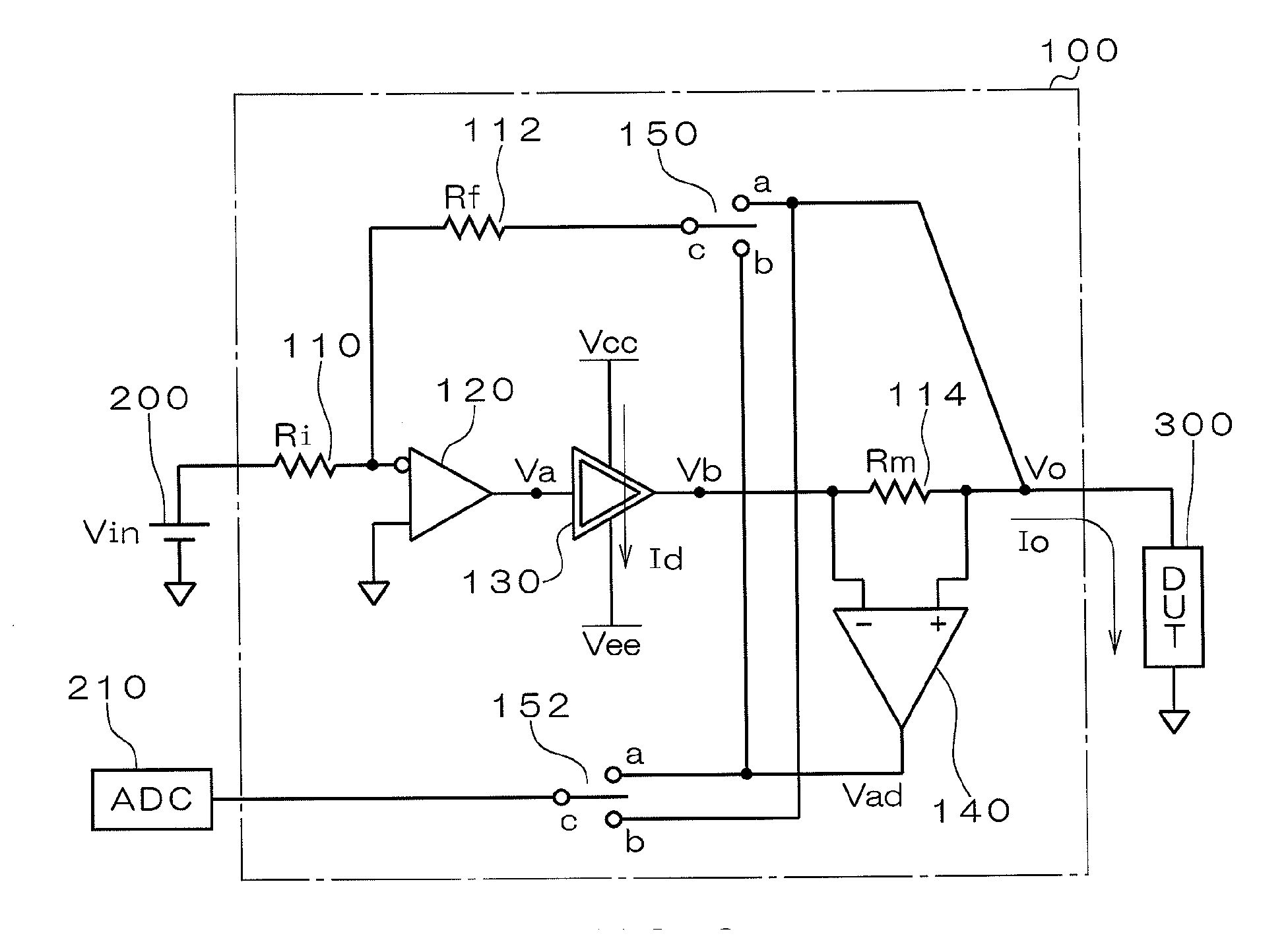
[0017] A DC test apparatus of one embodiment to which the present invention is applied will hereinafter be described in detail with reference to the accompanying drawings. FIG. 1 is a schematic view illustrating the overall configuration of a DC test apparatus in accordance with one embodiment of the present invention. As illustrated in FIG. 1, a DC test apparatus 100 of the present embodiment is provided with resistors 110, 112 and 114, differential amplifier circuits 120 and 140, a power amplifier circuit 130, and switches 150 and 152. The DC test apparatus is provided in a semiconductor test apparatus, for an example. The DC test apparatus 100 is connected to one of the pins of a DUT 300 and applies (supplies) a DC voltage or current to this pin. In addition, a DC power supply 200 the voltage value “Vin” of which is alterable and an analog-to-digital converter (ADC) 210 for converting an analog voltage to digital data (voltage data) are connected to the DC test apparatus 100. The...


PUM

PropertyMeasurementUnit
output currentaaaaaaaaaa
currentaaaaaaaaaa
output currentaaaaaaaaaa

Abstract

An object of the present invention is to provide a DC test apparatus capable of reducing wasteful standby power consumption. The DC test apparatus has a power amplifier circuit 130 for supplying a current to a DUT during a test. The power amplifier circuit 130 is provided with transistors 18 and 20 for generating an output current appropriate for an input voltage during current supply, resistors 54 and 56, and a variable resistance circuit 40 for setting a standby current flowing through these transistors 18 and 20 and the like during current supply to a smaller value at any time other than during current supply.

Description

BACKGROUND OF THE INVENTION [0001] 1. Field of the Invention [0002] The present invention relates to a DC test apparatus for performing force voltage / measure current type measurements and force current / measure voltage type measurements on a DUT (electronic device as a device under test). [0003] 2. Description of the Related Art [0004] As tests performed on a DUT, such as a semiconductor device, there are conventionally known a force voltage / measure current mode test wherein a predetermined DC voltage is applied and DC currents flowing through DUT pins at the time are measured and a force current / measure voltage mode test wherein a predetermined DC current is applied and DC voltages developing at DUT pins at the time are measured (refer to, for example, Japanese Patent Laid-Open No. 2005-315729). The DC test apparatus is intended to perform these tests and is often inherent in semiconductor test apparatus as part of the functions thereof. [0005] Incidentally, the above-described DC t...

Claims


Application Information

Patent Timeline
Patent Type & Authority Applications(United States)
IPC IPC(8): G01N27/42
CPCG01N27/045
Inventor ANDO, HIROKITANAKA, HIRONORI
Owner ADVANTEST CORP
Why Eureka
Try Eureka