Pattern forming apparatus and pattern forming method, movable member drive system and movable member drive method, exposure apparatus and exposure method, and device manufacturing method

a technology of pattern forming and pattern forming, which is applied in the direction of photomechanical treatment, printing, instruments, etc., can solve the problems of short-term fluctuation of measurement values of laser interferometers, insufficient focus margins at the time of exposure operation, and inability to accurately measure the effect of laser interferometers. , to achieve the effect of good accuracy, high integration and good accuracy

Inactive Publication Date: 2007-11-15
NIKON CORP
View PDF90 Cites 241 Cited by
  • Summary
  • Abstract
  • Description
  • Claims
  • Application Information

AI Technical Summary

Benefits of technology

[0011] With this apparatus, since a partial section of the aerial image measuring unit is arranged at the first movable body that holds the object on which a pattern is formed, measurement of an aerial image by the aerial image measuring unit while moving the movable body, and therefore, measurement of optical properties of the optical system (such as the best focus position) based on the measurement result of the aerial image can be performed. Accordingly, when forming a pattern on the object with an energy beam via the optical system, the position of the first movable body in the optical axis direction of the optical system is adjusted with high accuracy based on the measurement result of the optical properties. Further, since only a partial section of the aerial image measuring unit is arranged at the first movable body, the size of the first movable body is not increased, which makes it possible to favorably secure the position controllability.
[0042] With this method, position information of the second movable body is measured by the second measuring unit that includes the interferometer, and position information of the first movable body that moves within a predetermined plane holding the object is measured by the first measuring unit that includes the encoder system whose measurement value has short term stability superior to that of the interferometer. Accordingly, position control of the first movable body that holds the object on which a pattern is formed can be stably performed.

Problems solved by technology

However, there has been a possibility that the focus margin at the time of exposure operation becomes insufficient because a depth of focus becomes too narrow due to the shorter wavelength of exposure light and the larger NA of the projection optical system.
In this case, however, a stage used for measuring the best focus position and a stage used for the focus leveling control of the wafer on exposure are different, and therefore focus leveling control error could occur on exposure, and thus, exposure defect could occur due to defocus.
However, position control of the stage with higher precision has been required due to finer patterns to cope with semiconductor devices with higher integration, and therefore, short-term fluctuation of measurement values of the laser interferometer which is caused by temperature fluctuations of the atmosphere on the beam path is becoming unignorable now.

Method used


Image

  • Pattern forming apparatus and pattern forming method, movable member drive system and movable member drive method, exposure apparatus and exposure method, and device manufacturing method
  • Pattern forming apparatus and pattern forming method, movable member drive system and movable member drive method, exposure apparatus and exposure method, and device manufacturing method
  • Pattern forming apparatus and pattern forming method, movable member drive system and movable member drive method, exposure apparatus and exposure method, and device manufacturing method

Examples


Embodiment Construction

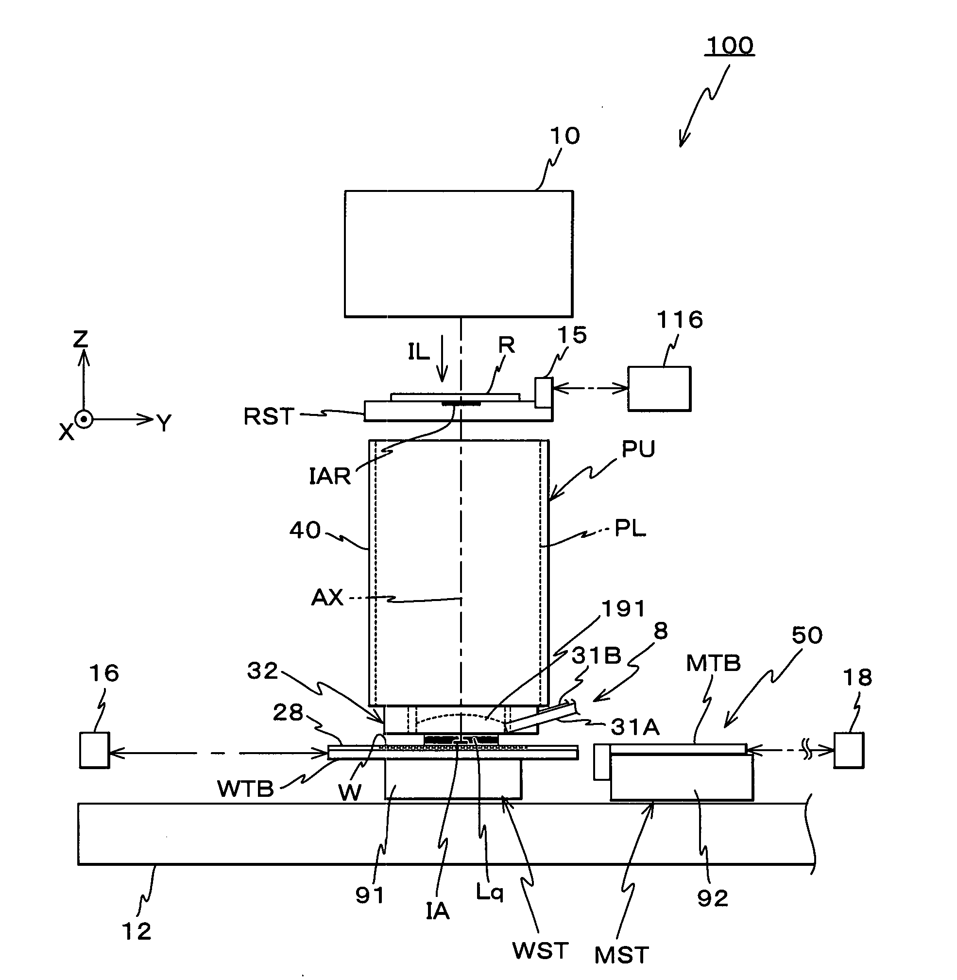
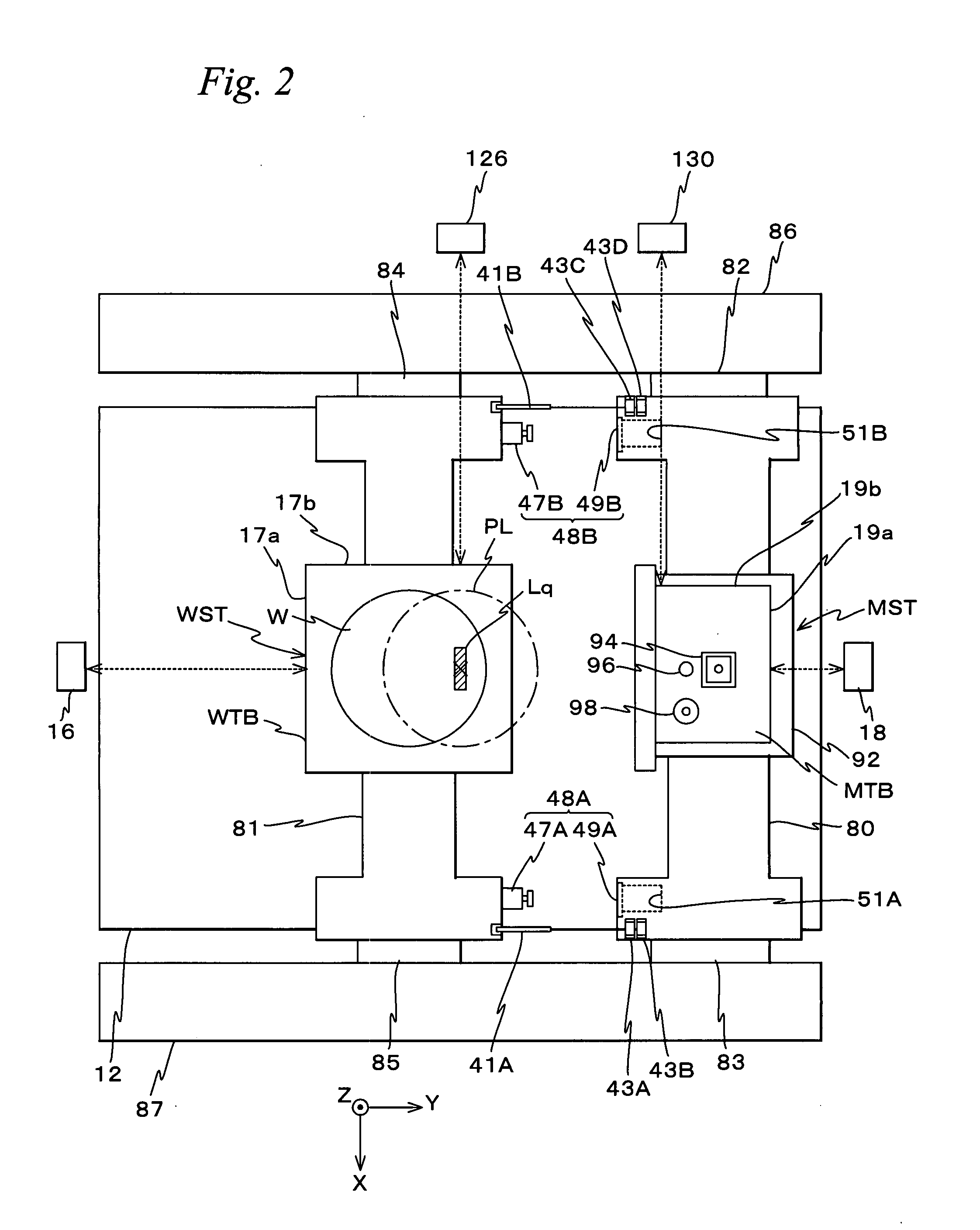
[0083] An embodiment of the present invention will be described below, with reference to FIGS. 1 to 36.

[0084]FIG. 1 schematically shows the configuration of an exposure apparatus 100 related to an embodiment. Exposure apparatus 100 is a scanning exposure apparatus by a step-and-scan method, that is, a so-called scanner. As will be described later, in the embodiment, a projection optical system PL is arranged, and the following description will be made assuming that a direction parallel to an optical axis AX of projection optical system PL is a Z-axis direction, a direction in which a reticle and a wafer are relatively scanned within a plane orthogonal to the Z-axis direction is a Y-axis direction and a direction that is orthogonal to a Z-axis and a Y-axis is an X-axis direction, and rotation (tilt) directions around the X-axis, the Y-axis and the Z-axis are θx, θy and θz directions respectively.

[0085] Exposure apparatus 100 is equipped with an illumination system 10, a reticle sta...


PUM

PropertyMeasurementUnit
angleaaaaaaaaaa
wavelengthaaaaaaaaaa
Refractive indexaaaaaaaaaa

Abstract

A partial section of an aerial image measuring unit is arranged at a wafer stage and part of the remaining section is arranged at a measurement stage, and the aerial image measuring unit measures an aerial image of a mark formed by a projection optical system. Therefore, for example, when the aerial image measuring unit measures a best focus position of the projection optical system, the measurement can be performed using the position of the wafer stage, at which a partial section of the aerial image measuring unit is arranged, in a direction parallel to an optical axis of the projection optical system as a datum for the best focus position. Accordingly, when exposing an object with illumination light, the position of the wafer stage in the direction parallel to the optical axis is adjusted with high accuracy based on the measurement result of the best focus position.

Description

CROSS-REFERENCE TO RELATED APPLICATIONS [0001] This non-provisional application claims the benefit of Provisional Application No. 60 / 780,046 filed Mar. 8, 2006, the disclosure of which is hereby incorporated herein by reference in its entirety.BACKGROUND OF THE INVENTION [0002] 1. Field of the Invention [0003] The present invention relates to pattern forming apparatuses and pattern forming methods, movable body drive systems and movable body drive methods, exposure apparatuses and exposure methods, and device manufacturing methods, and more particularly to a pattern forming apparatus and a pattern forming method that are suitable for being used in a lithography process when manufacturing electron devices such as semiconductor devices and liquid crystal display devices, a movable body drive system, a movable body drive method, an exposure apparatus and an exposure method that can suitably be used when manufacturing the electron devices, and a device manufacturing method in which the ...

Claims


Application Information

Patent Timeline
Patent Type & Authority Applications(United States)
IPC IPC(8): G03B27/42
CPCG03F7/70641G03F7/70675G03F7/70733G03F7/70775G03F7/70975G03F9/7026G03F9/7084G03F7/70725G03F7/7085G03F7/70341G03F7/70666Y10T29/49826G03F7/70516H01L21/0274G03F7/70358
Inventor SHIBAZAKI, YUICHI
Owner NIKON CORP
Why Eureka
Try Eureka