High-Pressure Sensor for Pressure-Independent Measurement

Inactive Publication Date: 2007-11-15
ROBERT BOSCH GMBH
View PDF2 Cites 12 Cited by
  • Summary
  • Abstract
  • Description
  • Claims
  • Application Information

AI Technical Summary

Benefits of technology

[0007] According to the present invention, through suitable dimensioning of the diaphragm geometry and appropriate positioning of strain gauges (DMS) on the diaphragm, the bridge circuit is influenced in such a way that the total resistance of the measurement bridge is independent of the deflection of the diaphragm and thus the total resistance depends only on the temperature of the diaphragm. Therefore, regardless of the pressure to be measured, the temperature of the diaphragm may be determined using the measurement bridge, e.g., the measurement bridge designed as a Wheatstone bridge, and this temperature may be used for compensation purposes. Therefore, a pressure-independent temperature measurement of the diaphragm is possible using the measurement bridge functioning as a sensor element without requiring additional compensation-measuring or temperature-measuring resistors to be applied to the metal diaphragm.
[0008] In an advantageous manner, no additional area of the metal diaphragm is required by compensation-measuring or temperature-measuring resistors and their electrical connection points due to the due to the configuration according to the present invention. Therefore, a higher degree of miniaturization is achievable, which is of considerable importance given the space constraint in the cylinder head area of today's internal combustion engines, where pressure sensors are used. Miniaturization of sensor elements also offers advantages with regard to manufacturing costs. The miniaturized combustion chamber pressure sensors greatly increase the possible applications of such sensor elements in internal combustion engines.
[0009] Furthermore, additional electric contact points are eliminated by the configuration of the present invention, thereby greatly simplifying the manufacturing process, as well as making it possible to avoid potential failure points, e.g., due to contact breakage. In combustion chamber pressure sensors, the electronic analyzer is located at a great distance from the actual pressure measurement point, where peak temperatures of up to 600° C. may occur, because of the maximum allowed temperature of approximately 140° C. Thus, with the pressure sensors used in the past, a temperature measurement in the area of the electronic analyzer would yield a signal far too inaccurate for temperature compensation of the Wheatstone measurement bridge. The measurement accuracy of the combustion chamber pressure sensor may be greatly improved by measuring and analyzing the pressure-independent bridge resistance as provided in the present invention.

Problems solved by technology

In combustion chamber pressure sensors, the electronic analyzer is located at a great distance from the actual pressure measurement point, where peak temperatures of up to 600° C. may occur, because of the maximum allowed temperature of approximately 140° C. Thus, with the pressure sensors used in the past, a temperature measurement in the area of the electronic analyzer would yield a signal far too inaccurate for temperature compensation of the Wheatstone measurement bridge.

Method used


Image

  • High-Pressure Sensor for Pressure-Independent Measurement
  • High-Pressure Sensor for Pressure-Independent Measurement
  • High-Pressure Sensor for Pressure-Independent Measurement

Examples


Embodiment Construction

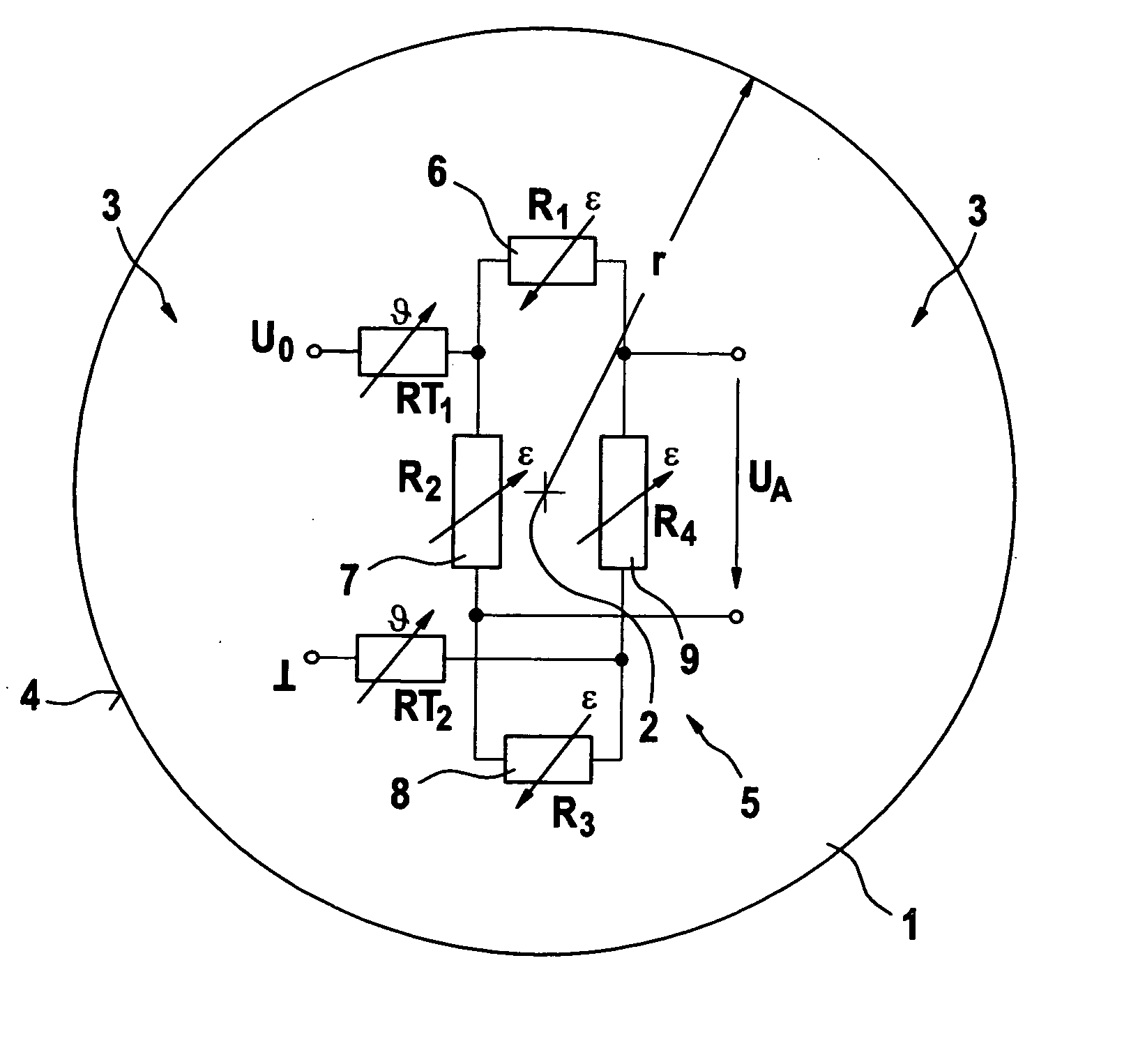
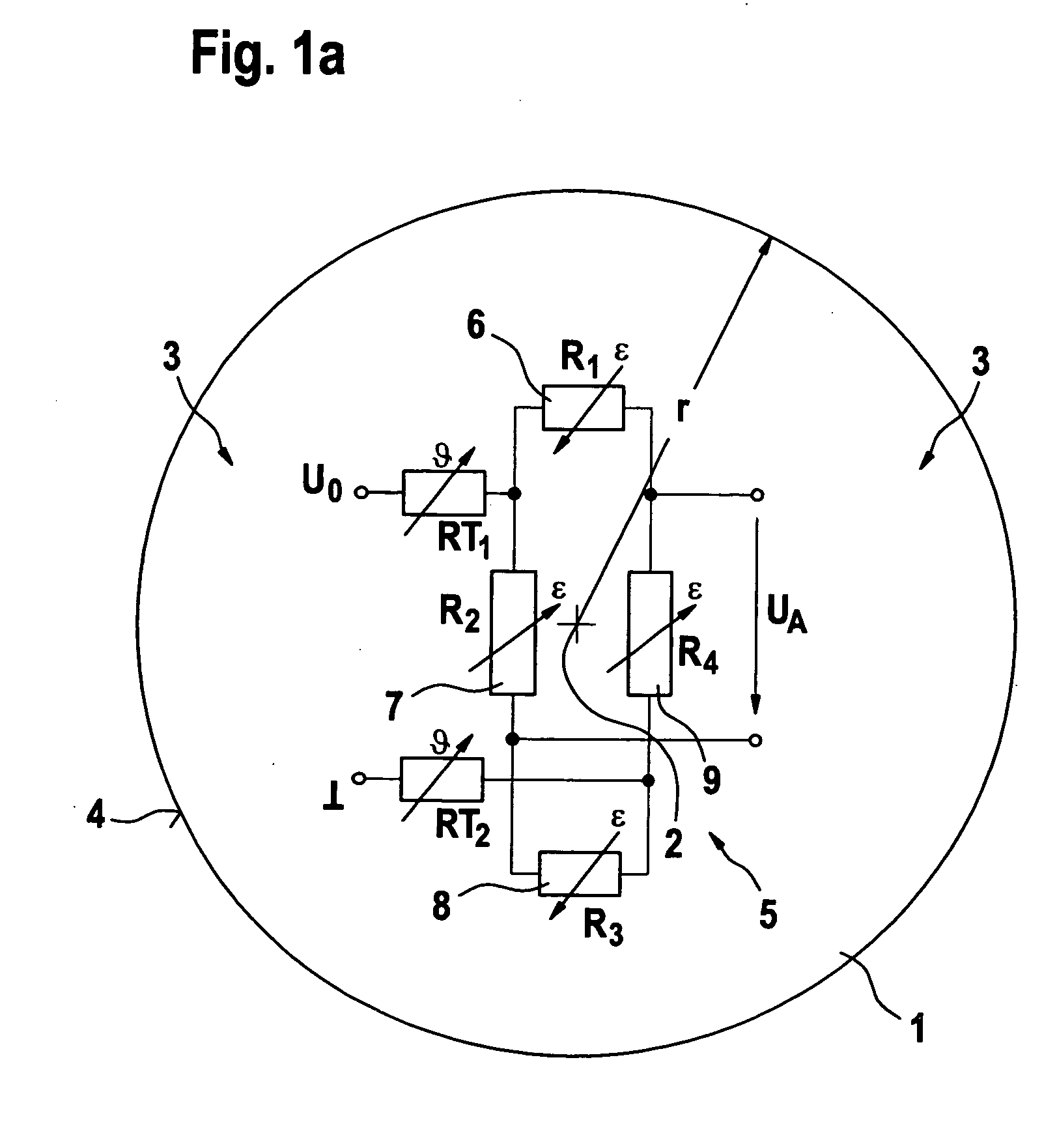
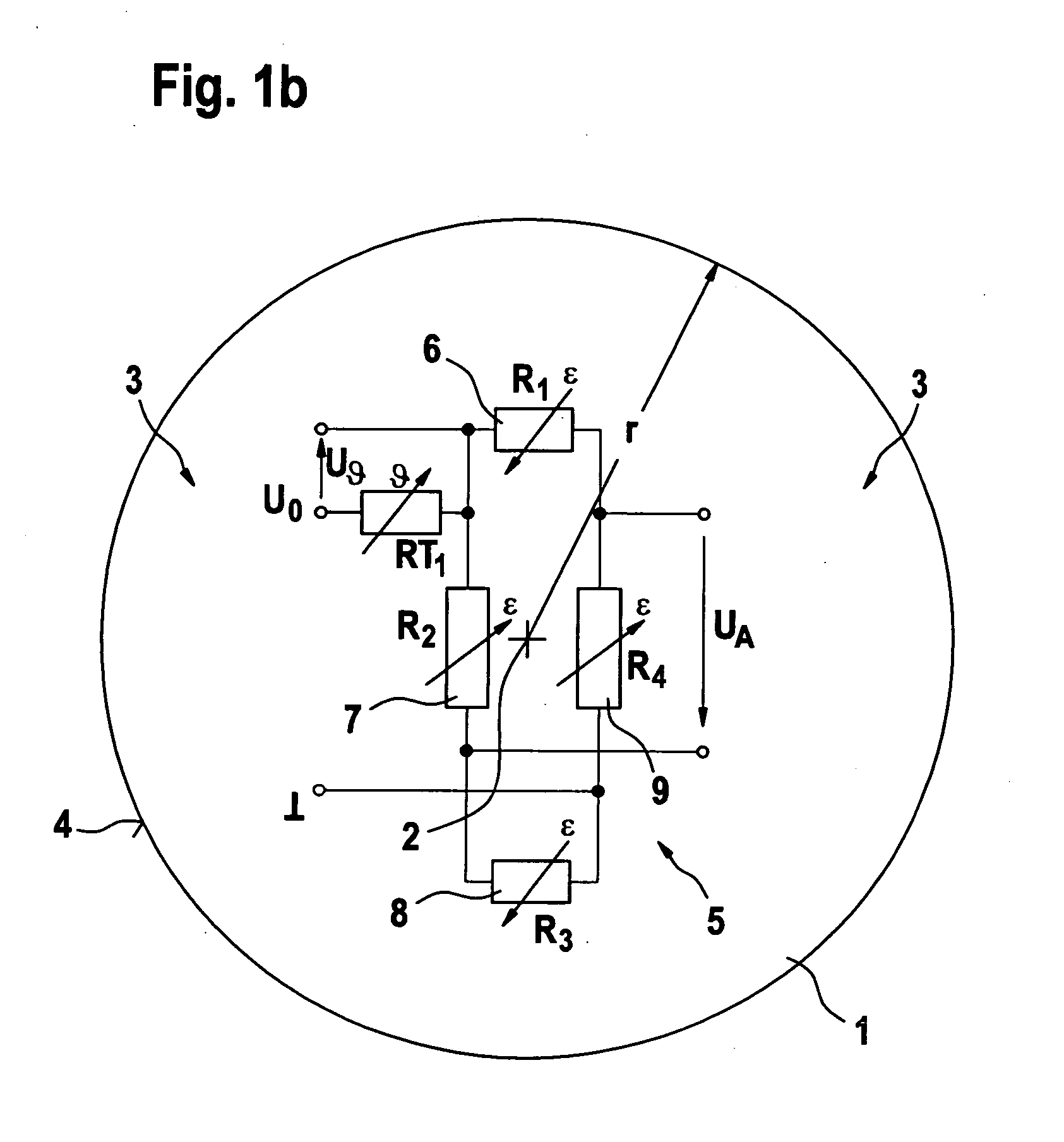
[0013] The bridge circuits on a steel diaphragm as shown in FIGS. 1a, 1b, 1c and 1d represent the conventional configurations.

[0014] A bridge circuit 5, which may be designed as a Wheatstone bridge circuit, is applied to a metal diaphragm 1. Bridge circuit 5 includes multiple resistors R1, R2, R3 and R4, characterized by reference numerals 6, 7, 8 and 9. Metal diaphragm 1 may be a steel diaphragm, the center of which is labeled as 2, and having a radius r. The peripheral areas, i.e., the areas at a greater distance from center 2 of metal diaphragm 1, are each indicated by reference numeral 3. The edge of metal diaphragm 1 is labeled with reference numeral 4.

[0015] Resistors R1, R2, R3 and R4 connected in bridge circuit 5 may be strain gauges. Bridge circuit 5 is connected to a power supply voltage U0. Measurement voltage UA is tapped between resistors R1 and R4, or between R2 and R3.

[0016] Resistors R1, R2, R3 and R4 provided on metal diaphragm 1 are positioned so that they exper...


PUM


Abstract

A method for pressure-independent temperature determination using a metal diaphragm is provided. A bridge circuit having multiple resistors is provided on this diaphragm. One pair of resistors is near the center of the diaphragm and another pair of resistors is situated at a distance from the center. The resistors are provided on the metal diaphragm in such a way that the tensile elongation of the pair of resistors near the center corresponds in absolute value to compressions of the pair of resistors far from the center.

Description

FIELD OF THE INVENTION [0001] The present invention relates to pressure-independent temperature determination using a diaphragm. BACKGROUND INFORMATION [0002] In addition to piezoelectric quartz crystals, sensor chips are being used today as combustion chamber pressure sensors. When used to detect the pressure prevailing in the combustion chamber of an internal combustion engine, the silicon chip should not be exposed directly to the high temperatures prevailing there, which are on the order of approximately 600° C. This is accomplished with the help of a metallic separating diaphragm and a welded ram of a sufficient length. By micromechanical application of a tiny platform at the center of the diaphragm, the sensor becomes a force sensor. [0003] A combustion chamber pressure sensor designed as a sensor chip is known from the Bosch Automotive Engineering Manual (chief editor Horst Bauer, 23rd updated and expanded edition), Braunschweig, Wiesbaden, Vieweg 1999, ISBN 3-528-03876-4, pa...

Claims


Application Information

Patent Timeline
IPC IPC(8): G01K7/20G01K1/26G01K7/16G01L9/04G01L19/04
CPCG01K1/26G01L9/065G01K2205/00G01K7/206
Inventor MOELKNER, THOMASKASCHUBE, CARSTENDIDRA, HANS-PETERKOTT, MICHAEL
Owner ROBERT BOSCH GMBH
Why Eureka
Try Eureka