Optical module

a technology of optical modules and shields, applied in the direction of electromagnetic transceivers, semiconductor laser structural details, radio frequency controlled devices, etc., can solve the problem of difficult to provide an optical module with shields b>16/b>

Inactive Publication Date: 2007-11-15
FUJITSU LTD
View PDF4 Cites 7 Cited by
  • Summary
  • Abstract
  • Description
  • Claims
  • Application Information

AI Technical Summary

Benefits of technology

[0011] It is an object of the present invention to at least solve the above problems in the conventional technologies.

Problems solved by technology

Such an optical transceiver has a problem of crosstalk in which a signal passing through a transmitter leaks into a receiver adjacent to the transmitter to produce noises, etc.
As a result, providing an optical module with the shield 16 is difficult when the optical module is under a size restriction.

Method used


Image

  • Optical module
  • Optical module
  • Optical module

Examples


Embodiment Construction

[0024] Exemplary embodiments according to the present invention will be explained in detail with reference to the accompanying drawings.

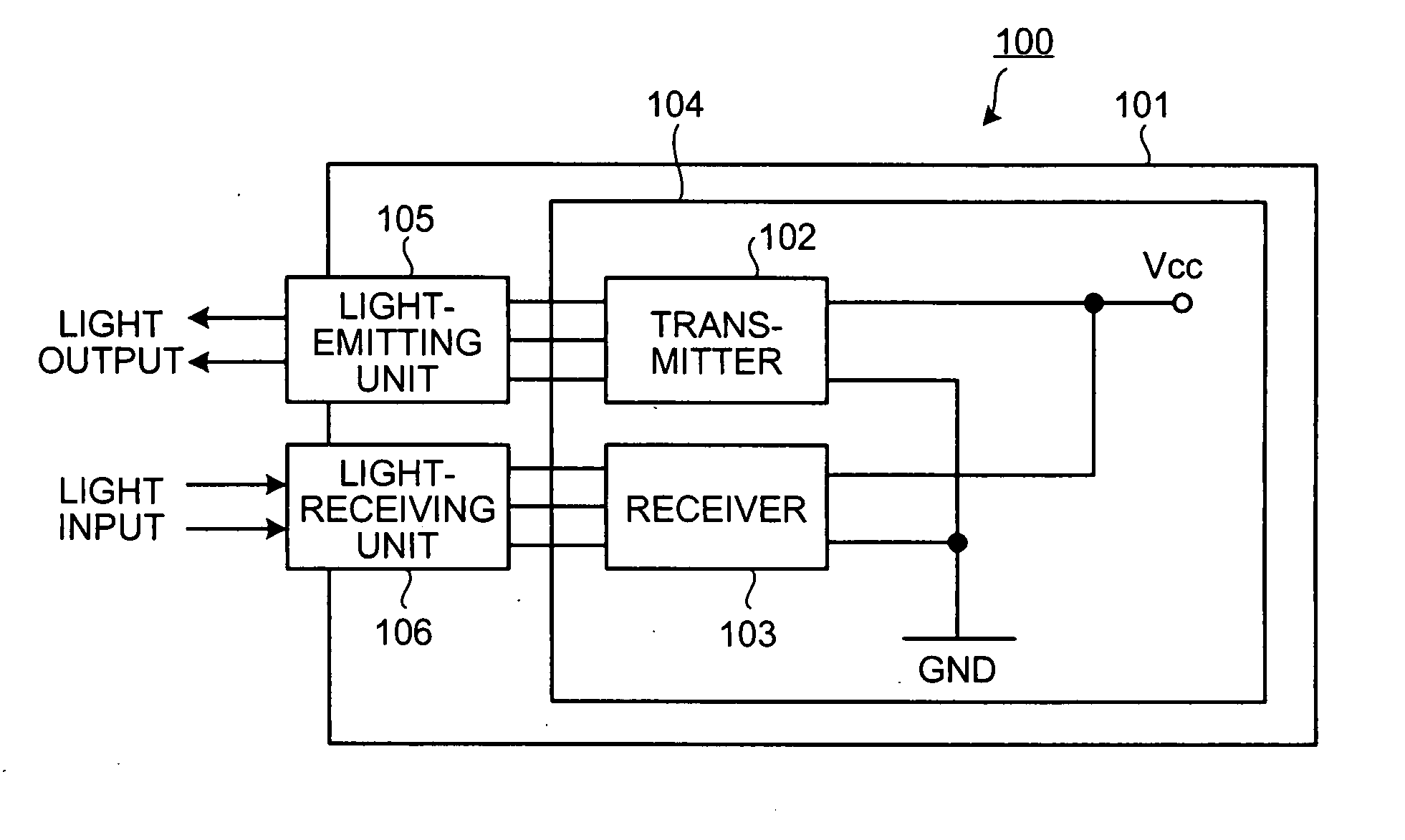
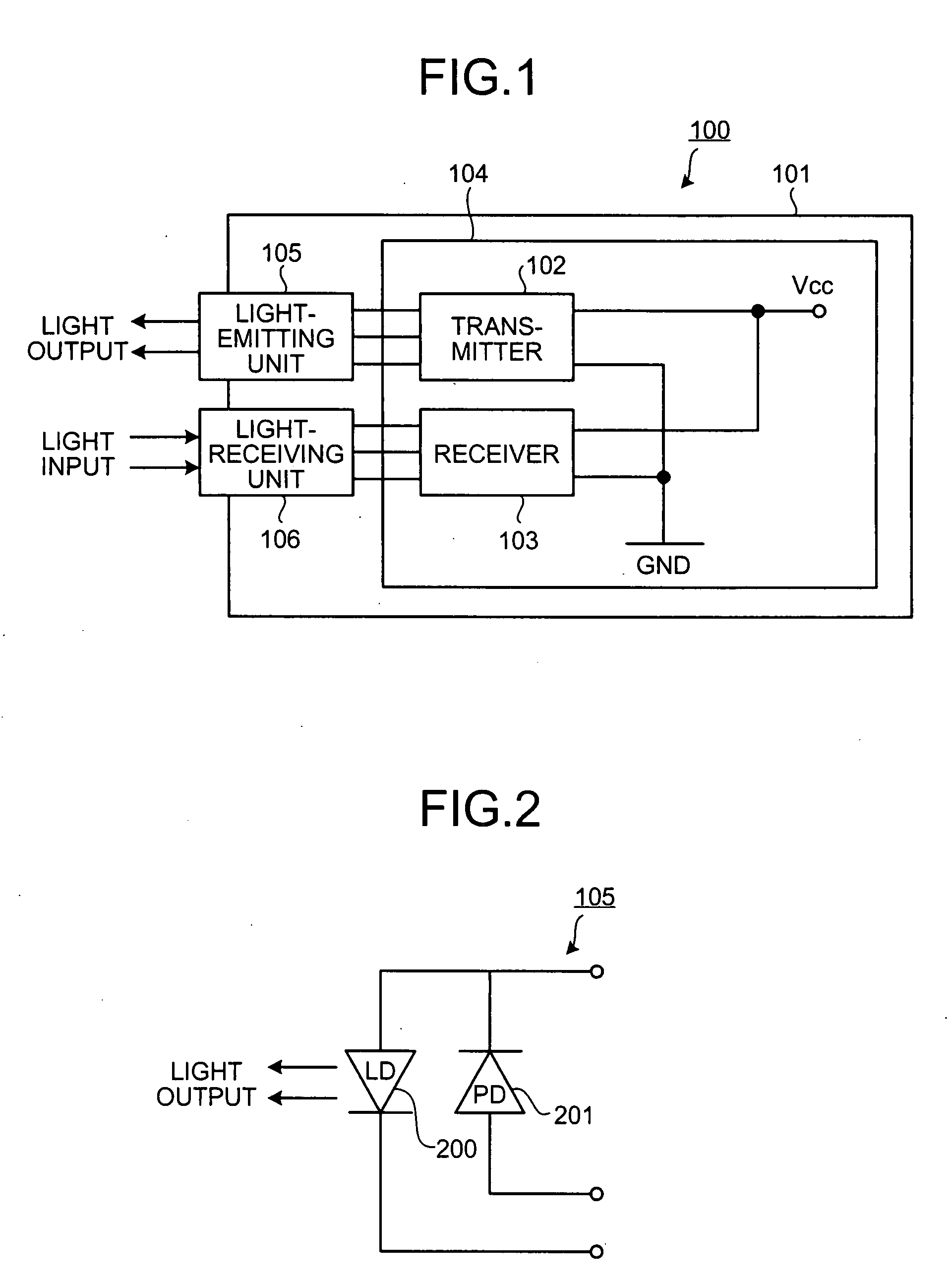
[0025]FIG. 1 depicts a configuration of an optical module according to a first embodiment of the present invention. An optical module 100 includes a printed substrate 104 having a transmitter 102 and a receiver 103 stored in a standardized casing 101, a light-emitting unit 105 that is connected to the transmitter 102 and that outputs light to a transmission line (not shown), and a light-receiving unit 106 that is connected to the receiver 103 and that receives input light from a transmission line (not shown). Both the transmitter 102 and the receiver 103 on the printed substrate 104 are provided with power from a common power supply (Vcc), and are connected to a common ground (GND).

[0026]FIG. 2 depicts a circuit configuration of the light-emitting unit. The light-emitting unit 105 is composed of a laser diode (LD) 200 that is a light-emitting elem...


PUM


Abstract

In an optical module in which a transmitter and a receiver that respectively outputs and receives optical signals are stored in a casing, the transmitter and the receiver are connected to a common power line and to a common ground line, and a ferrite bead is arranged on the ground line in the receiver. The ferrite bead absorbs a high-frequency current component out of components in an electric signal passing through the ground line on which the ferrite bead is arranged. An inductance component that evolves on a ground line and a power line of a light receiving element and oscillation of a series resonance circuit that is formed of a capacitance component of the light receiving element are suppressed to reduce crosstalk.

Description

BACKGROUND OF THE INVENTION [0001] 1. Field of the Invention [0002] The present invention relates to an optical module in which an optical signal transmitter and an optical signal receiver are integrated. [0003] 2. Description of the Related Art [0004] The Internet traffic using the internet protocol (IP), which has spread rapidly in recent years, offers large-capacity transmission services by employing an optical fiber network for a transmission line. [0005] Meantime, an optical transceiver for transmitting and receiving optical signals has been reduced in size as the mounting density of the device has been becoming higher and higher. Such an optical transceiver has a problem of crosstalk in which a signal passing through a transmitter leaks into a receiver adjacent to the transmitter to produce noises, etc. Some techniques have been disclosed as measures against crosstalk, which include a technique of attaching an electric wave absorber to crosstalk electric wave generation spot o...

Claims


Application Information

Patent Timeline
Patent Type & Authority Applications(United States)
IPC IPC(8): H04B10/00H01S5/02H04B10/2507H04B10/40H04B10/50H04B10/60H04B10/67H04B10/69
CPCH01L27/144H04B10/40H01L31/02002
Inventor HAKOMORI, KATSUHIKOHORISHITA, MASAKAZU
Owner FUJITSU LTD
Why Eureka
Try Eureka