Saw tooth with hard layer

a technology of hard layer and saw tooth, which is applied in the direction of metal sawing equipment, sawing equipment, milling equipment, etc., can solve the problems of affecting the service life of saw teeth, and affecting so as to improve the service life and the cutting quality of saw teeth

Inactive Publication Date: 2007-11-22
AKE KNEBEL
View PDF12 Cites 4 Cited by
  • Summary
  • Abstract
  • Description
  • Claims
  • Application Information

AI Technical Summary

Benefits of technology

[0006]The object of the invention is to improve both t

Problems solved by technology

By means of one or more cutting edges provided on the tooth face, an acute angle of attack results between the tool and the face that is to be cut, which in turn results in more of a cutting than a shearing cut and causes an elongated, thin chip to be formed.
A disadvantage of saw teeth shaped in this way is that the saw teeth, and in particular the t

Method used


Image

  • Saw tooth with hard layer
  • Saw tooth with hard layer

Examples


Embodiment Construction

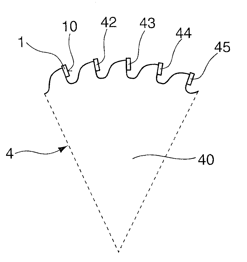
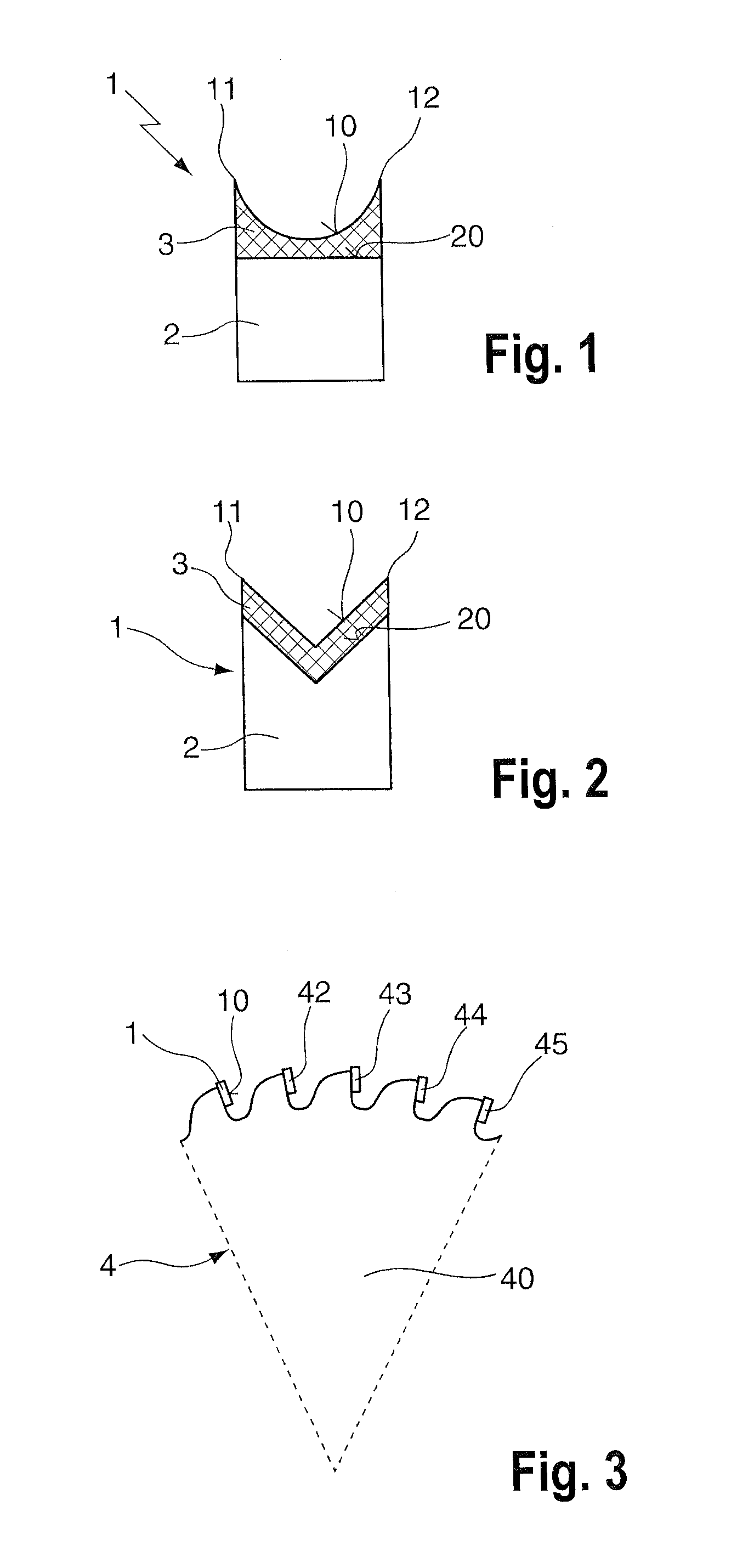
[0021]FIG. 1 shows a saw tooth 1 of the invention in a horizontal section. A base body 2 of the saw tooth 1 has a square cross section. A hard layer 3 is applied to a front face 20 of the base body 2, over the full surface. An outer surface, facing away from the base body 2, of the hard layer 3 is a completely rounded face portion, which forms a tooth face 10 of the saw tooth 1. The tooth height, that is, the length measured at the tooth face 10, is as a rule from 1 to 10 mm. Because of the concave, hollow embodiment of the tooth face 10 as shown, at the two edges of the tooth face 10 a cutting edge 11, shown in section as a pointed tip, and a further cutting edge 12, also shown as a pointed tip, are embodied.

[0022]The cutting edges 11, 12 formed of the material of the hard layer 3, on entering into a material that is to be cut, lead to a precise cut. An embodiment of two cutting edges 11, 12, by means of a uniform contact, which in particular distributes forces equally, of the cutt...


PUM

PropertyMeasurementUnit
Thicknessaaaaaaaaaa
Shapeaaaaaaaaaa

Abstract

A saw tooth has a base body comprising a solderable hard metal and a hard layer comprising a material that is harder than the hard metal of the base body; the hard layer is provided on a front face of the base body, and the tooth face has at least one chamfered and/or rounded face portion.

Description

CROSS-REFERENCE TO A RELATED APPLICATION[0001]The invention described and claimed hereinbelow is also described in German Patent Applications DE 20 2006 008 127.5 filed on May 20, 2006 and DE 10 2006 034 010.8 filed on Jul. 22, 2006. These German Patent Applications, whose subject matter is incorporated here by reference, provide the basis for a claim of priority of invention under 35 U.S.C. 119(a)-(d).BACKGROUND OF THE INVENTION[0002]The invention relates to a saw tooth with a surface clad with a hard layer.[0003]Tools, usually machine-driven, used for processing wood, such as saw blades, often have saw teeth of hard metal. The saw teeth essentially determine the cutting properties of the tool. The number, shape and position of the saw teeth define the shape of a cut made with the tool. The material comprising the saw teeth determines the maximum hardness of a material that can be cut with the tool.[0004]From the prior art, such as DE 101 23 752 A1, saw teeth embodied as hollow tee...

Claims


Application Information

Patent Timeline
IPC IPC(8): B23D57/00
CPCB23C5/18B23C2200/083B23C2200/085B23C2210/084B23C5/08B23C2226/315B23C2240/08B27B33/08B23C2210/086Y10T83/9319
Inventor OTTENWAELDER, ADALBERTKNEBEL, ALEXANDER
Owner AKE KNEBEL
Why Eureka
Try Eureka