
Battery cell design and method of its construction

a battery cell and cell end technology, applied in the field of electrochemical battery cells, can solve the problems of reducing the total energy capacity of a cell, crimping techniques are not efficient use of cell volume, and the attempt to create a robust hermetic seal between the cell's can and the cell's end cap after the cell has been activated, and achieves the effect of low inductance and easy manufacturing of electrochemical cells

Active Publication Date: 2007-11-22
RIL USA INC +1
View PDF30 Cites 74 Cited by
  • Summary
  • Abstract
  • Description
  • Claims
  • Application Information

AI Technical Summary

Benefits of technology

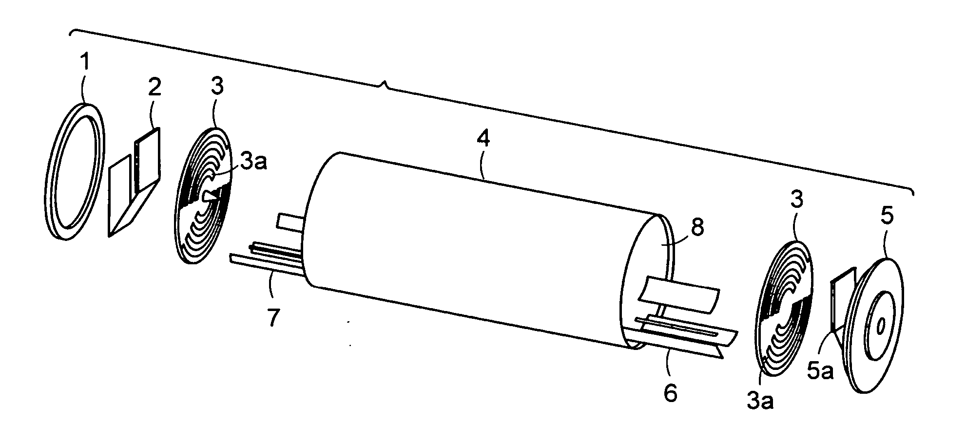
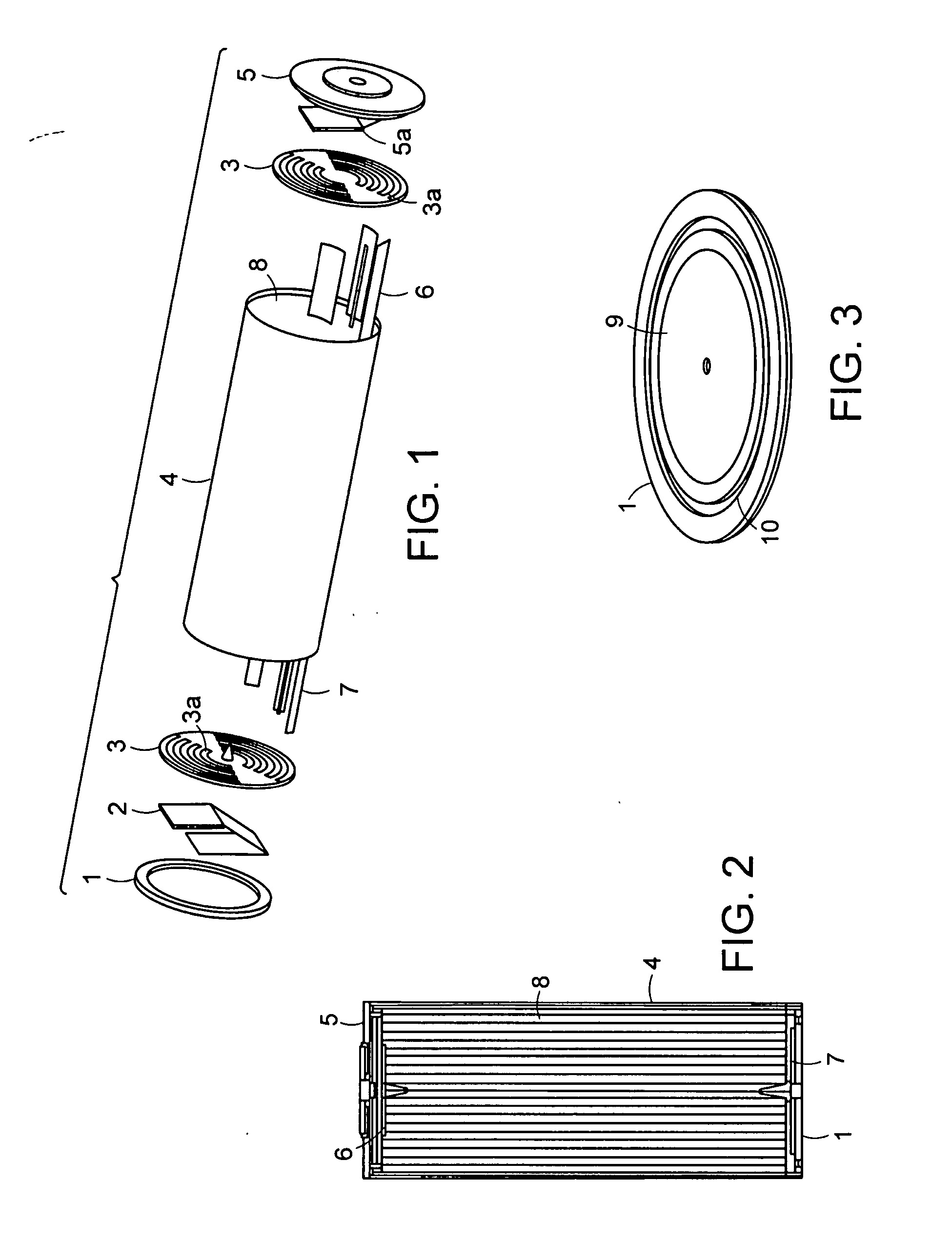
[0014] A low inductance, easily manufacturable electrochemical cell is provided. In one or more embodiments, a cylindrical electrochemical cell can include a spirally wound assembly having an anode sheet and a cathode sheet separated by separator membranes, the cathode sheet having a first electroactive layer on a first current collector, and the anode sheet having a second electroactive layer on a second current collector, the spirally wound assembly having a cylindrical side wall and opposing end faces. At least one of the first current collector and the second current collector can be in electrical communication with conducting tabs that extend from the anode sheet or the cathode sheet, the conducting tabs extend from an end face of the spirally wound assembly. Centers of the conducting tabs can be located within a 90 degree quadrant of an end face of the spirally wound assembly.
[0019] In one or more embodiments, locations of the conducting tabs can be selected such that net magnetic fields caused by induced currents in the electrochemical cell is reduce by at least 80% compared to having only a single conducting tab located at a leading edge of the anode sheet or the cathode sheet.
[0028] In one or more embodiments, locations of the conducting tabs can be selected such that net magnetic fields caused by induced currents in the electrochemical cell is reduce by at least 80% compared to having only a single conducting tab located at a leading edge of the anode sheet or the cathode sheet.

Problems solved by technology

Attempts to create a robust hermetic seal between the cell's can and the cell's end cap after the cell has been activated are complicated by the presence of electrolyte.
These crimping techniques are not an efficient use of cell volume and reduce the total energy capacity of a cell.
In welded cell designs, the task of hermetically sealing the fill hole is challenging.
In volumetrically efficient cell designs, the wall thickness where this fill hole exists is often very thin, making sealing even more challenging.
The result is a highly uncontrollable, unreliable, and in-the-way fill-hole seal.
Often, when a cell experiences this type of event, materials other than gas try to escape from the cell through this vent and end up clogging these windows.
This defeats the purpose of the vent, preventing gas from escaping, and the cell ends up reaching critical internal pressures and often explodes.
These small vents can result in similar clogs and ultimately the same explosions.
Due to chemical compatibility and corrosion problems, these tabs are limited to a few metal types, depending on whether the tabs are on the anode (−) or cathode (+) potential of the cell.

Method used


Image

  • Battery cell design and method of its construction
  • Battery cell design and method of its construction
  • Battery cell design and method of its construction

Examples


Embodiment Construction

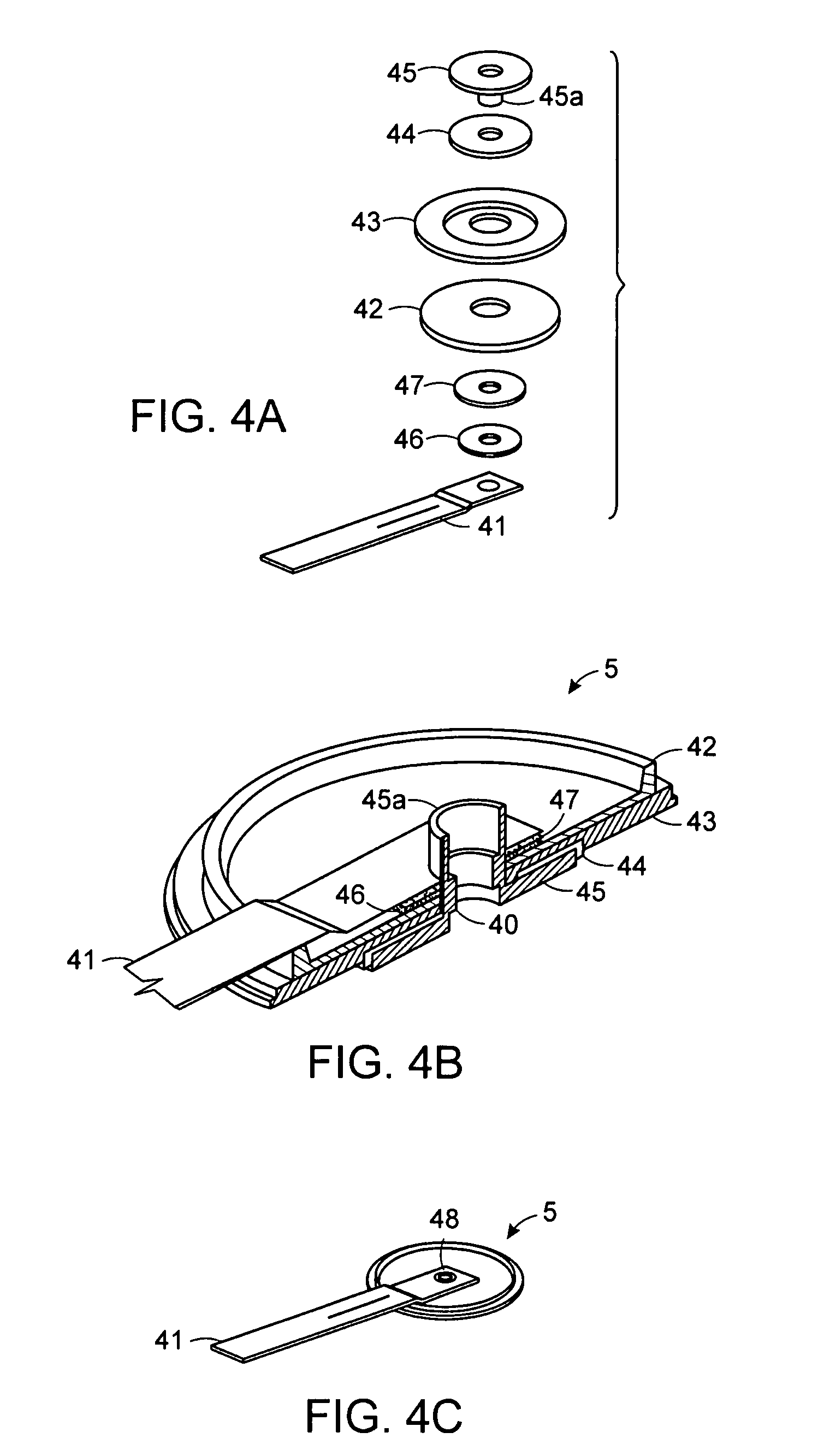
[0058] Conventional battery cell end cap design incorporates one or more of a fill-hole, a safety vent, and a power terminal into the design of an end cap. These features are usually separate, individual, and bulky entities occupying their own internal volume on the cell's end cap. Battery cells that utilize a symmetrically centralized activation fill-hole have a distinct advantage during manufacture over cells whose activation fill holes are off center and require orientation during fill. Battery cells that utilize a symmetrically centralized battery terminal have a distinct advantage in commercial applications over cells whose power terminal is off center and require specific orientation during use and / or packaging into larger format strings of cells.

[0059] In one or more embodiments of the present invention, a cylindrical cell is provided that includes upper and lower welded end caps. The cell's primary packaging (can and end caps) is composed of aluminum alloy. The weld seal is...


PUM

PropertyMeasurementUnit
Fractionaaaaaaaaaa
Angleaaaaaaaaaa
Areaaaaaaaaaaa

Abstract

A compact, robust, multifunctional and highly manufacturable rechargeable cylindrical electrochemical cell is provided. In some embodiments, a cell can include a spirally wound assembly having an anode sheet and a cathode sheet separated by separator membranes, each sheet having a electroactive layer on a current collector. At least one of the current collectors can be in electrical communication with conducting tabs that extend from at least one of the anode sheet and the cathode sheet, the conducting tabs extends from an end face of the spirally wound assembly. The centers of the plurality of conducting tabs can be located within a 90 degree quadrant of an end face of the spirally wound assembly.

Description

RELATED APPLICATION [0001] This is application is a continuation-in-part of and claims priority under 35 U.S.C. §120 to U.S. patent application Ser. No. 11 / 515,597, filed Sep. 5, 2006, and which claims the benefit of priority under 35 U.S.C. §119(e), to U.S. Application No. 60 / 714,171, filed Sep. 2, 2005, both of which are entitled “Battery Cell Design and Method of Its Construction,” which are hereby incorporated by reference in their entirety. [0002] This application also claims the benefit under 35 U.S.C. §119(e) of U.S. Provisional Patent Application No. 60 / 799,873, filed May 12, 2006, entitled “Low-Inductance Cylindrical Battery,” which is hereby incorporated by reference in its entirety.FIELD OF THE INVENTION [0003] The present invention generally relates to an electrochemical battery cell. More particularly, the present invention relates to a compact, robust, multifunctional and highly manufacturable rechargeable battery cell. BACKGROUND [0004] Increasing the discharge capaci...

Claims


Application Information

Patent Timeline
IPC IPC(8): H01M4/00H01M14/00H01M4/04H01M50/538
CPCH01M2/263Y10T29/49108H01M10/0431Y02E60/10H01M50/538
Inventor CHU, ANDREW C.GOZDZ, ANTONI S.RILEY, GILBERT N. JR.HOFF, C. MICHAEL
Owner RIL USA INC
Learn More