Automated inlet steam supply valve controls for a steam turbine powered chiller unit

Inactive Publication Date: 2007-11-29
JOHNSON CONTROLS TECH CO
View PDF18 Cites 32 Cited by
  • Summary
  • Abstract
  • Description
  • Claims
  • Application Information

AI Technical Summary

Benefits of technology

[0008]One advantage of the present invention is that the starting mode and the return to a standby idling mode of the steam turbine can be controlled remotely by a control system.
[0009]Another advantage of the present invention is that a reduced cooling water flow is required for the steam condenser during an ext

Problems solved by technology

The idling mode operation results in the steam turbine operating at a predetermin

Method used


Image

  • Automated inlet steam supply valve controls for a steam turbine powered chiller unit
  • Automated inlet steam supply valve controls for a steam turbine powered chiller unit
  • Automated inlet steam supply valve controls for a steam turbine powered chiller unit

Examples


Embodiment Construction

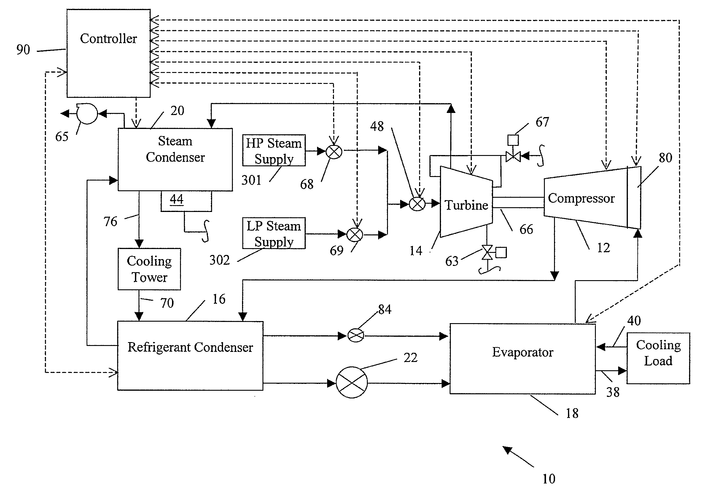
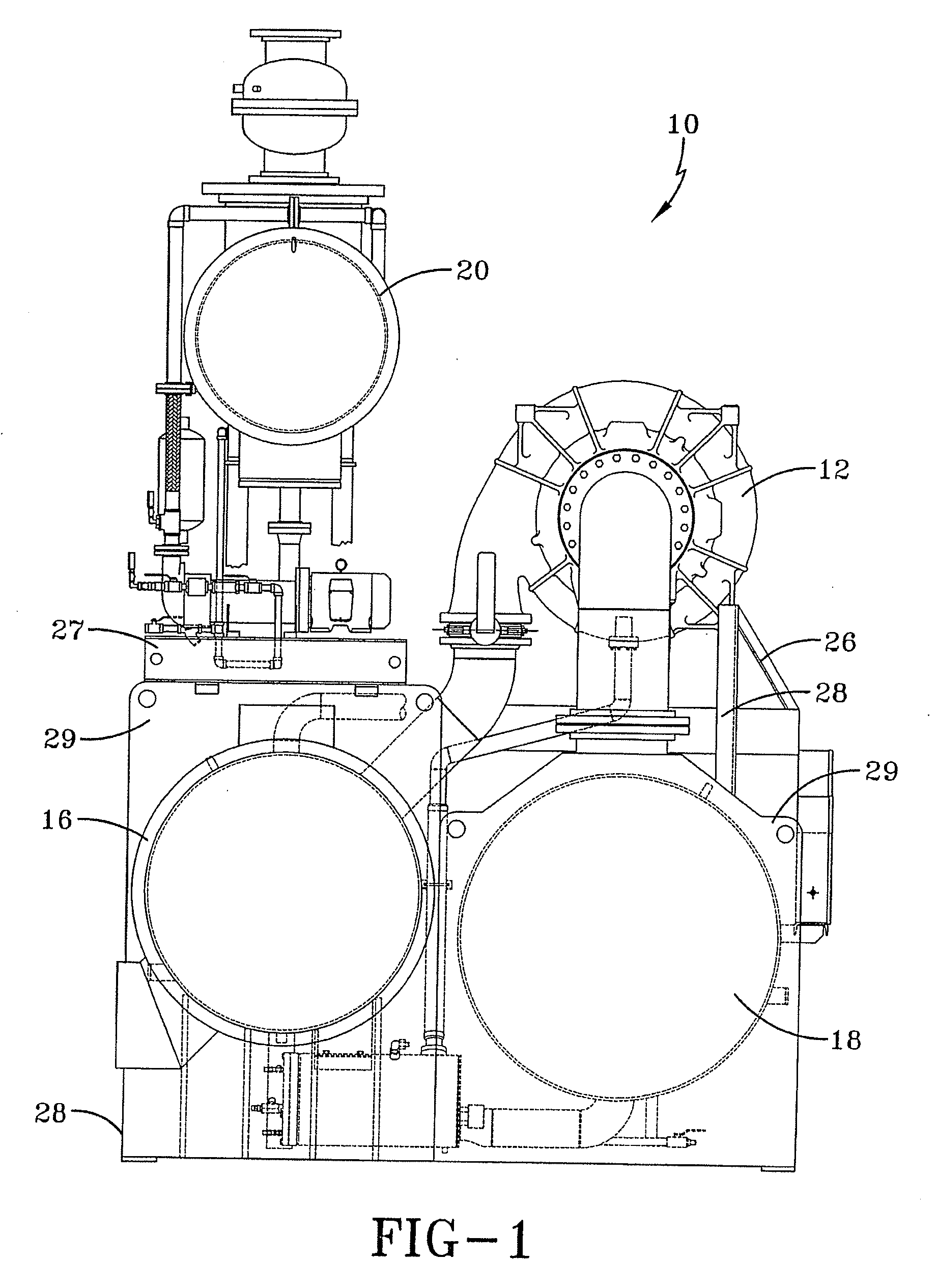
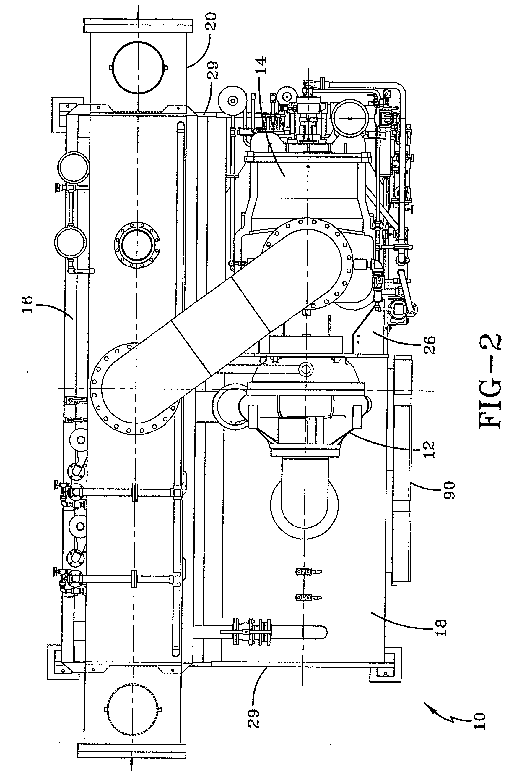
[0019]A general system to which the invention is applied is illustrated, by means of example, in FIGS. 1-3. As shown, the HVAC, refrigeration, or chiller system 10 includes a compressor 12, a steam turbine 14, a refrigerant condenser 16, a water chiller or evaporator 18, a steam condenser 20, an expansion device 22 and a control panel or controller 90. The operation of the control panel 90 will be discussed in greater detail below. The chiller system 10 further includes a compressor lubrication system (not shown) and a turbine lubrication system (not shown). The conventional liquid chiller system 10 includes many other features that are not shown in FIGS. 1-3. These features have been purposely omitted to simplify the drawing for ease of illustration.

[0020]In one embodiment, a “structural frame” permits the stacking or vertical arrangement of major components of the chiller system 10 to provide a prepackaged unit that occupies less floor space with a smaller footprint than a field f...


PUM


Abstract

A control system and method are provided for the controlling of steam supplies used by a steam turbine driven chiller unit. The steam turbine can receive steam from a high pressure steam source and/or a low pressure steam source depending on the operating mode of the steam turbine. The high pressure steam is used for operating at the steam turbine at rated speed and to provide the breakaway torque when starting the steam turbine. The low pressure steam is used for extending idling of the steam turbine that enables the steam turbine to transition more quickly to rated speed when desired.

Description

BACKGROUND OF THE INVENTION[0001]The present invention relates generally to a control system for a chiller unit, and more specifically, to a control system for a steam turbine powered chiller unit that can control inlet steam supply valves for a steam turbine receiving steam from two different steam supplies.[0002]While most heating, ventilation and air conditioning (HVAC), refrigeration, or chiller systems use electric motors to power the corresponding compressor(s) in the chiller system, some chiller systems have used a steam turbine to power the compressor. These previous steam turbine powered chiller systems were supplied with only a high pressure steam supply required for normal full load operation and had a PLC based panel for use with the steam turbine drive. The panel logic controlled only the remote speed set point of the electronic governor supplied by the turbine manufacture. This stand-alone speed control prevented the customer from safely taking advantage of an availabl...

Claims


Application Information

Patent Timeline
IPC IPC(8): F25B49/00F25B1/00
CPCF25B27/00F25B49/022F25B2327/00F25B2400/0411F25B2500/26F25B2700/21173F25B2700/1932F25B2700/21152F25B2700/21155F25B2700/2117F25B2700/21172F25B2600/0261
Inventor SHAFFER, DENNIS L.
Owner JOHNSON CONTROLS TECH CO
Why Eureka
Try Eureka