A method and integrated system for removing a target gas component from a source gas
A technology of gas composition and source gas, which is applied in separation methods, chemical instruments and methods, and separation of dispersed particles, and can solve problems such as low energy utilization and operating costs that need to be improved
- Summary
- Abstract
- Description
- Claims
- Application Information
AI Technical Summary
Problems solved by technology
Method used
Image
Examples
Embodiment 1
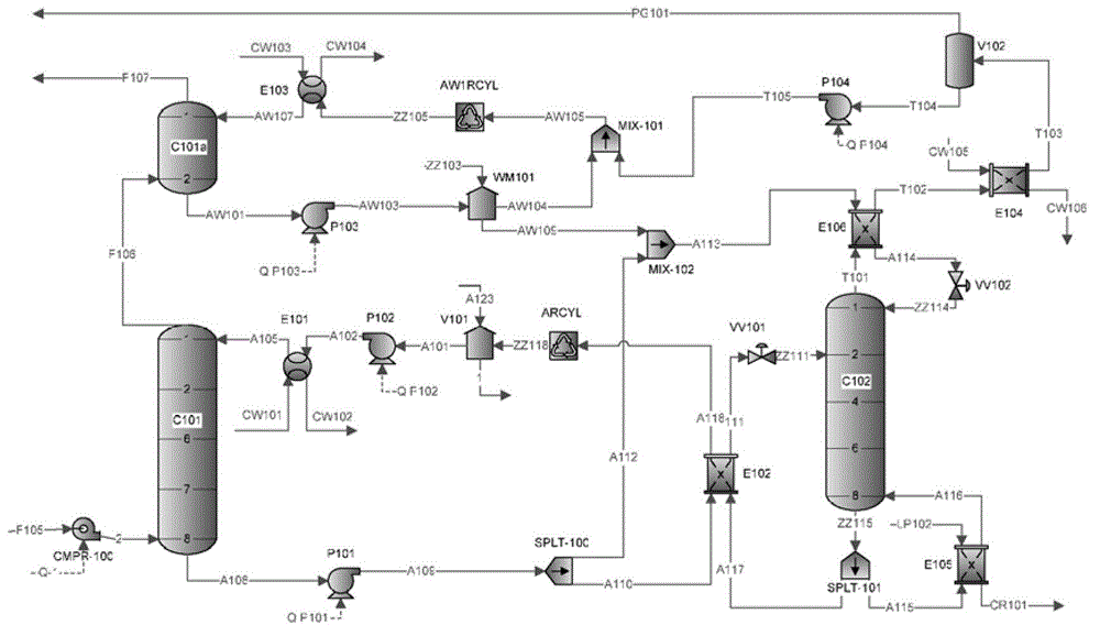
[0079] Example 1 (rich liquid split type)
[0080] Refer below image 3 To illustrate the use of the optimized CO of the present invention 2 capture process system for CO 2 Capture process steps. The capture process can be applied to the CO in the flue gas emitted by the combustion of thermal power plants 2 catch. The temperature of the raw gas from the flue gas is 50°C, the pressure of the raw gas is 0.03MPa, and the composition of the raw gas is: CO 2 is 51.95v / v%, H 2 is 19.74v / v%, CO is 9.71v / v%, CH 4 is 16.09v / v%, H 2 O is 0.87v / v%, N 2 It is 1.64v / v%, all in volume percentage. The flue gas flow rate entering the absorption tower is 5000Nm 3 / h.
[0081] Under the action of the fan, the raw material gas (also known as flue gas) is dehydrated and cooled (at a temperature of 35°C) and enters the absorption tower C101 from above the liquid level of the liquid storage tank of the absorption tower, and flows from bottom to top. The absorption liquid is supplied fro...
Embodiment 2
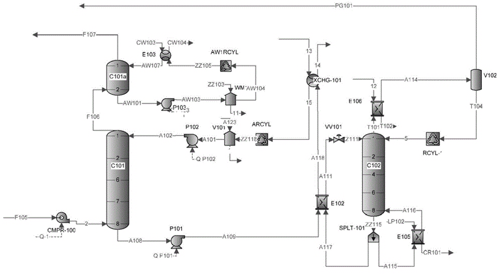
[0088] Example 2 (rich liquid multi-stage heat exchange type)
[0089] Refer below Figure 4 To illustrate the use of the liquid-rich multistage heat exchange type CO of the present invention 2 capture process system for CO 2 Capture process steps. exist Figure 4 In this process, the rich liquid flowing out from the bottom of the absorption tower C101 is first heated to a certain temperature by the first-stage lean-rich liquid heat exchanger E102, and the heated rich liquid is regenerated by the CO discharged from the top of the tower through the second-stage heat exchanger E106. 2 The gas is heated, and the rich liquid continues to be heated by the lean liquid flowing out from the bottom of the regeneration tower through the third-stage heat exchanger XCHG-102, and finally flows in from the top of the regeneration tower. This process not only fully preheats the rich liquid and saves the amount of regeneration steam, but also cools the lean liquid, further saving the cool...
Embodiment 3
[0097] Embodiment 3 (cross heat exchange type)
[0098] Refer below Figure 5 To illustrate the use of cross-exchange heat CO of the present invention 2 capture process system for CO 2 Capture process steps. exist Figure 5 In the process, the rich liquid flowing out from the bottom of the absorption tower is firstly heat-exchanged by the first-stage lean-rich liquid and then split, part of it flows through the second-stage lean-rich liquid heat exchanger to exchange heat with the high-temperature lean liquid, and the rest passes through the heat exchanger and the regeneration The overhead product gas is subjected to heat exchange.
[0099] The specific process is as follows:
[0100] Using the flue gas with the same composition as in Example 1 (the temperature and pressure are also the same as in Example 1), under the action of the fan, the above-mentioned raw material gas is dehydrated and cooled (at a temperature of 35°C) from above the liquid level of the absorption t...
PUM
 Abstract
Description
Claims
Application Information
 - R&D
- Intellectual Property
- Life Sciences
- Materials
- Tech Scout
- Unparalleled Data Quality
- Higher Quality Content
- 60% Fewer Hallucinations
Browse by: Latest US Patents, China's latest patents, Technical Efficacy Thesaurus, Application Domain, Technology Topic, Popular Technical Reports.
© 2025 PatSnap. All rights reserved.Legal|Privacy policy|Modern Slavery Act Transparency Statement|Sitemap|About US| Contact US: help@patsnap.com


