Lubricating apparatus for 4-cycle engine
a technology for lubricating apparatus and 4-cycle engines, applied in the direction of auxiliary lubrication, lubrication elements, pressure lubrication, etc., can solve the problems of shallow and wide oil pans, increase in weight, etc., and achieve the effect of reducing the likelihood of air entrainmen
- Summary
- Abstract
- Description
- Claims
- Application Information
AI Technical Summary
Benefits of technology
Problems solved by technology
Method used
Image

Examples
first embodiment
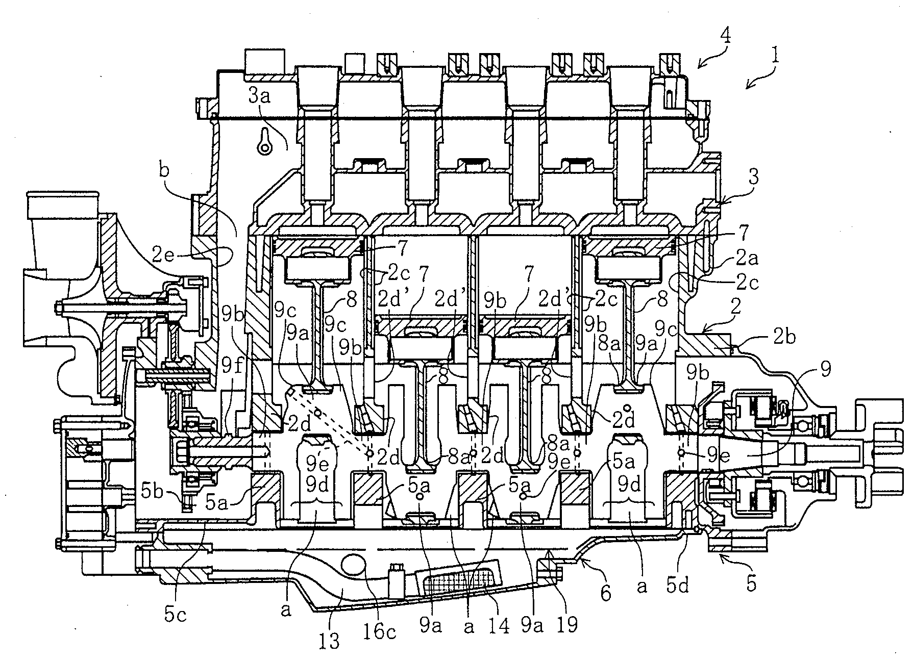
[0025]FIG. 1 to FIG. 7 illustrates a lubricating apparatus for a 4-cycle engine according to the present invention. As illustrated in FIG. 1, the engine 1 preferably is a four-cylinder water-cooled 4-cycle type.
[0026]The engine 1 has a cylinder block 2, a cylinder head 3 connected to an upper joint surface of a cylinder section 2a of the cylinder block 2, and a head cover 4 attached to an upper joint surface of the cylinder head 3. In addition, an upper case section 2b forming an upper half section of a crankcase can be integrally formed and joined to a lower part of the cylinder section 2a of the cylinder block 2. A lower case 5 forming a lower half section of a crankcase can be connected to the lower joint surface of the upper case section 2b. Furthermore, an oil pan 6 can be connected to the lower joint surface of the lower case 5.
[0027]Pistons 7 arranged to freely slide in each of four cylinder bores 2c formed in the cylinder block 2 can be connected to a crankshaft 9 via a conn...
second embodiment
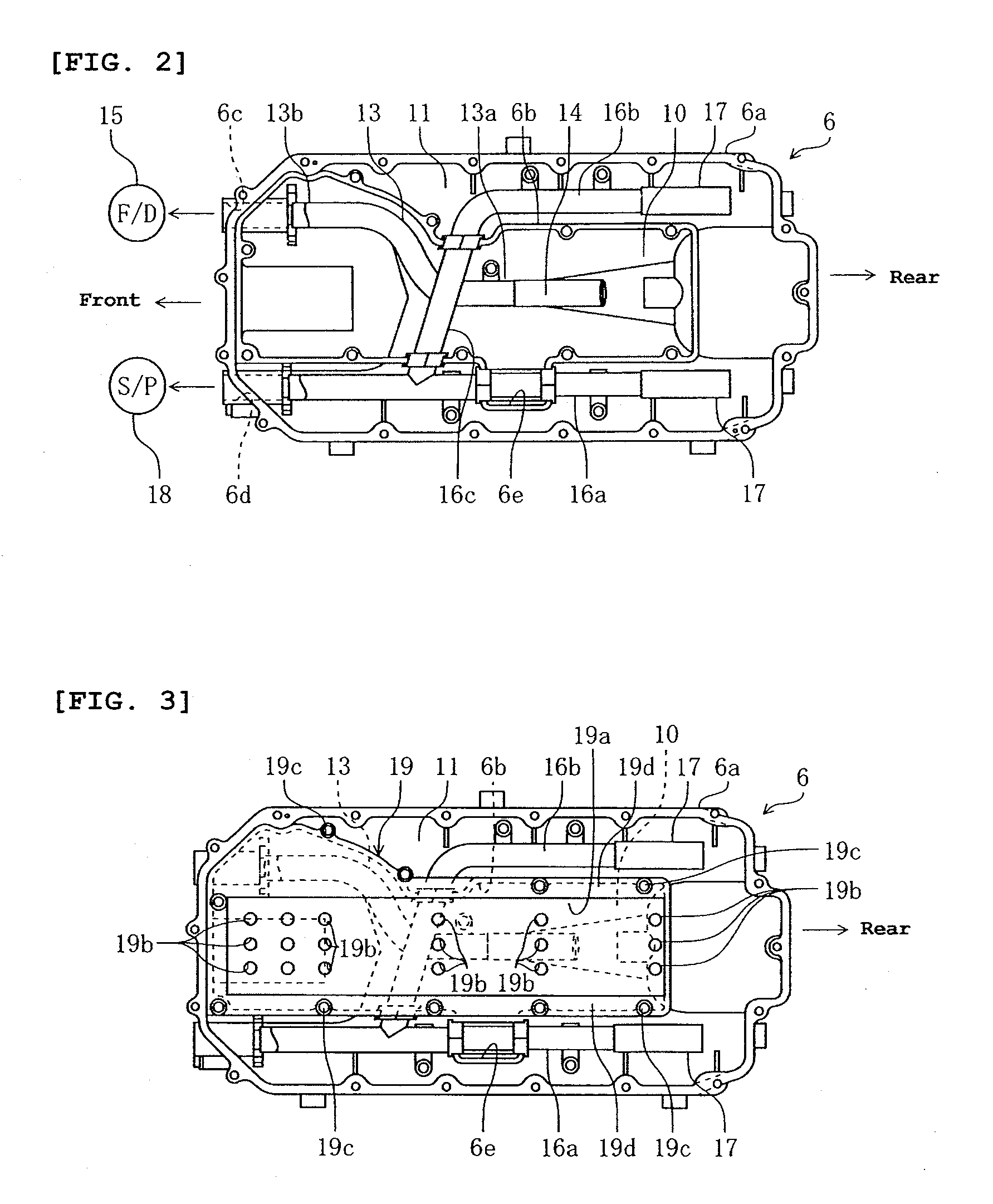
[0062]Also, in the second embodiment, oil collecting holes 19b′ are formed in a front portion of the lid 19, more specifically, in a portion of the lid 19 forward of the oil strainer 14, which serves as an intake opening of the feed pump 15.
[0063]When a water vehicle to which the present invention pertains is running, the front part of the water vehicle is raised and oil in the main oil chamber tends to be shifted to the oil strainer 14 side. So, if the oil collecting holes 19b′ are located at a part of the lid 19 on the oil strainer 14 side, there is a possibility that the shifted oil may leak out of the main oil chamber 10 through the oil collecting holes 19b′. In this embodiment, however, the oil collecting holes 19b′ are formed specifically on the front side, thus reducing the likelihood of oil leakage, such as that described above.
[0064]The first and second embodiments mentioned above describe a lubricating apparatus of a 4-cycle engine for a water vehicle. However, it is under...
PUM
 Abstract
Description
Claims
Application Information
 - R&D
- Intellectual Property
- Life Sciences
- Materials
- Tech Scout
- Unparalleled Data Quality
- Higher Quality Content
- 60% Fewer Hallucinations
Browse by: Latest US Patents, China's latest patents, Technical Efficacy Thesaurus, Application Domain, Technology Topic, Popular Technical Reports.
© 2025 PatSnap. All rights reserved.Legal|Privacy policy|Modern Slavery Act Transparency Statement|Sitemap|About US| Contact US: help@patsnap.com