Motor and electric power steering system

a technology of electric power steering and motor, which is applied in the direction of electrical steering, dynamo-electric components, dynamo-electric machines, etc., can solve the problems of large air gap between the rotor and the stator, increased torque loss, and center deviation to the rotor, so as to reduce torque loss, small leakage of magnetic flux, and small size

Inactive Publication Date: 2007-11-29
JTEKT CORP
View PDF17 Cites 11 Cited by
  • Summary
  • Abstract
  • Description
  • Claims
  • Application Information

AI Technical Summary

Benefits of technology

[0020]According to the motor of the first aspect of the invention, since the stator core is press-fitted into the motor case from the opening such that a part of the stator core is exposed from the motor case, and a part of the stator core that is not press-fitted to the motor case is capable of providing a sliding fitting connection with the bracket, it is not necessary to provide additional space for the sliding fitting structure. Therefore, it is possible to provide the motor in small size and center alignment can be conducted without the motor case, namely conducted with dimensional tolerances of only two parts: the stator and the bracket. Therefore, it is possible to obtain a motor in which the air gap between the rotor and the stator can be made small.
[0021]According to the motor of the second aspect of the inv

Problems solved by technology

Accordingly, there is a problem that torque loss is increased.
Furthermore, due to dimensional tolerances of three parts: the stator core, the motor case and

Method used


Image

  • Motor and electric power steering system
  • Motor and electric power steering system
  • Motor and electric power steering system

Examples


embodiment 1

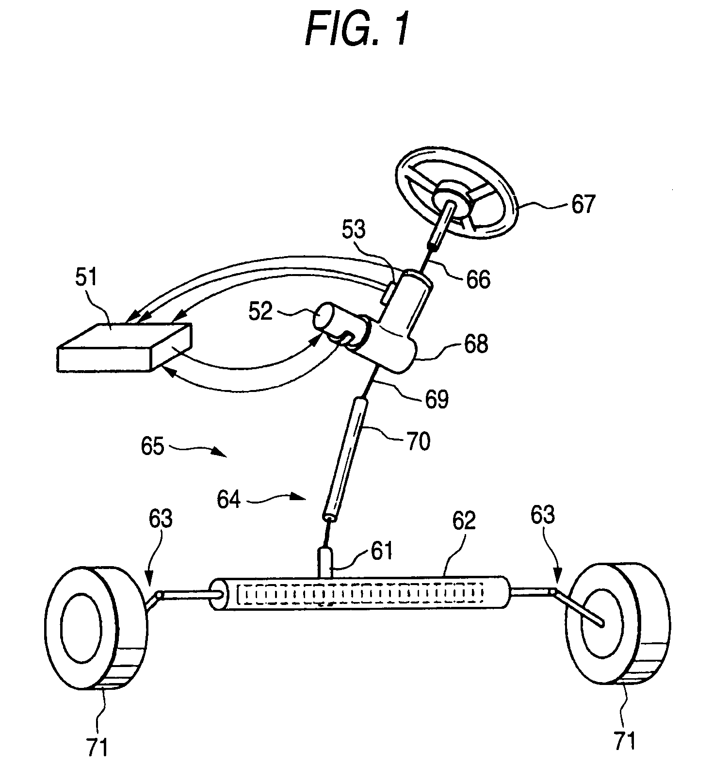
[0033]FIG. 1 is a schematic view showing construction of an electric power steering system according to Embodiment 1 of the invention. The electric power steering system includes a steering member (steering wheel, or steering handle) 67 for a steering operation, a motor 52 for assisting the steering operation as brushless motor that is driven according to the steering operation of the steering member 67, a transmitting device 64 for transmitting rotation of the motor 52 to steering mechanisms 63,63 through a reduction gear mechanism 68 and a drive control unit 51 for driving and controlling the motor 52. The steering member 67 is connected to an input shaft 66.

[0034]The transmitting device 64 includes an output shaft 69 connected to the input shaft 66 through a torsion bar (not shown), a connecting shaft 70 coupled to the output shaft 69 through a universal joint, a pinion shaft 61 coupled to the connecting shaft 70 through another universal joint and a rack shaft 62 which has rack ...

embodiment 2

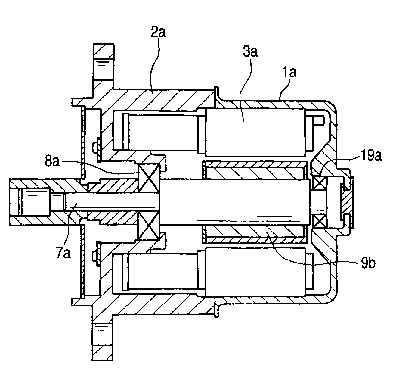
[0049]FIG. 4 is a longitudinal cross-sectional view showing construction of a brushless motor as a motor according to Embodiment 2 of the invention.

[0050]In this brushless motor, an inner circumferential surface of a through hole formed at a center portion of a bracket 2a which closes an opening of a cylindrical motor case 1a having a bottom supports an output shaft side bearing 8a. Further, an inner circumferential surface of a through hole formed at a center portion on the bottom of the motor case 1a supports an opposite side bearing 19a.

[0051]A stator core 3a is supported by an inner circumferential surface of the motor case 1a by being press-fitted thereto from the opening. A rotor 9b is disposed at a position opposing the stator core 3a on a shaft 7a (rotation shaft) supported by the bearings 8a,19b.

[0052]The stator core 3a is press-fitted to the motor case 1a such that a part of the stator core 3a is exposed from the motor case 1a. A part of the stator core 3a that is not pr...

embodiment 3

[0053]FIG. 5 is a longitudinal cross-sectional view showing construction of a brushless motor as a motor according to Embodiment 3 of the invention.

[0054]In this brushless motor, an inner circumferential surface of a through hole formed at a center portion on a bottom of a cylindrical motor case 1b with bottom supports an output shaft side bearing 8b. Further, an inner circumferential surface of a through hole formed at a center portion of a bracket 2b that closes an opening of the motor case 1b supports an opposite side bearing 19b.

[0055]A stator core 3b is supported by an inner circumferential surface of the motor case 1b by being press-fitted thereto from the opening to a step portion formed on the inner circumferential surface of the motor case 1b such that a part of the stator core 3b is exposed from the motor case 1b. A part of the stator core 3b that is not press-fitted to the motor case 1b forms a sliding fitting wall that is capable of providing a sliding fitting connectio...


PUM


Abstract

The invention provides a motor including: a cylindrical motor case having a bottom that supports an outer circumferential surface of a stator core by an inner circumferential surface thereof; and a bracket that supports an output shaft side bearing and closes an opening of the motor case; wherein the stator core is press-fitted into the motor case from the opening such that a part of the stator core is exposed from the motor case, and a part of the stator core that is not press-fitted to the motor case forms a sliding fitting wall capable of providing a sliding fitting connection with the bracket.

Description

BACKGROUND OF THE INVENTION[0001]1. Field of the Invention[0002]This invention relates to a motor, and an electric power steering system in which a motor is provided for assisting a steering operation such that the motor is driven and controlled based on a steering torque detected by a torque sensor.[0003]2. Related Art[0004]An electric power steering system for reducing load of a driver is provided with an input shaft connected to a steering member (steering wheel, steering handle etc.), an output shaft connected to control wheels through a pinion and a rack or the like, a connecting shaft that connects the input shaft and the output shaft. Based on a torsion angle caused in the connecting shaft, a steering torque applied to the input shaft is detected by a torque sensor. Then, based on the detected steering torque value, the motor for assisting the steering operation coupled to the output shaft is driven and controlled.[0005]In such an electric power steering system, brushless mot...

Claims


Application Information

Patent Timeline
IPC IPC(8): B62D5/04
CPCB62D5/0403H02K5/15
Inventor MATSUBARA, KENNIGUCHI, NOBORUKANDA, NAOTAKESOKU, TOSHIMASA
Owner JTEKT CORP
Why Eureka
Try Eureka