Laser scanning microscope and microscopic observing method
a scanning microscope and microscopic technology, applied in the field of laser scanning microscope, can solve problems such as taking some time, and achieve the effect of reducing the execution time of photostimulation
- Summary
- Abstract
- Description
- Claims
- Application Information
AI Technical Summary
Benefits of technology
Problems solved by technology
Method used
Image
Examples
first embodiment
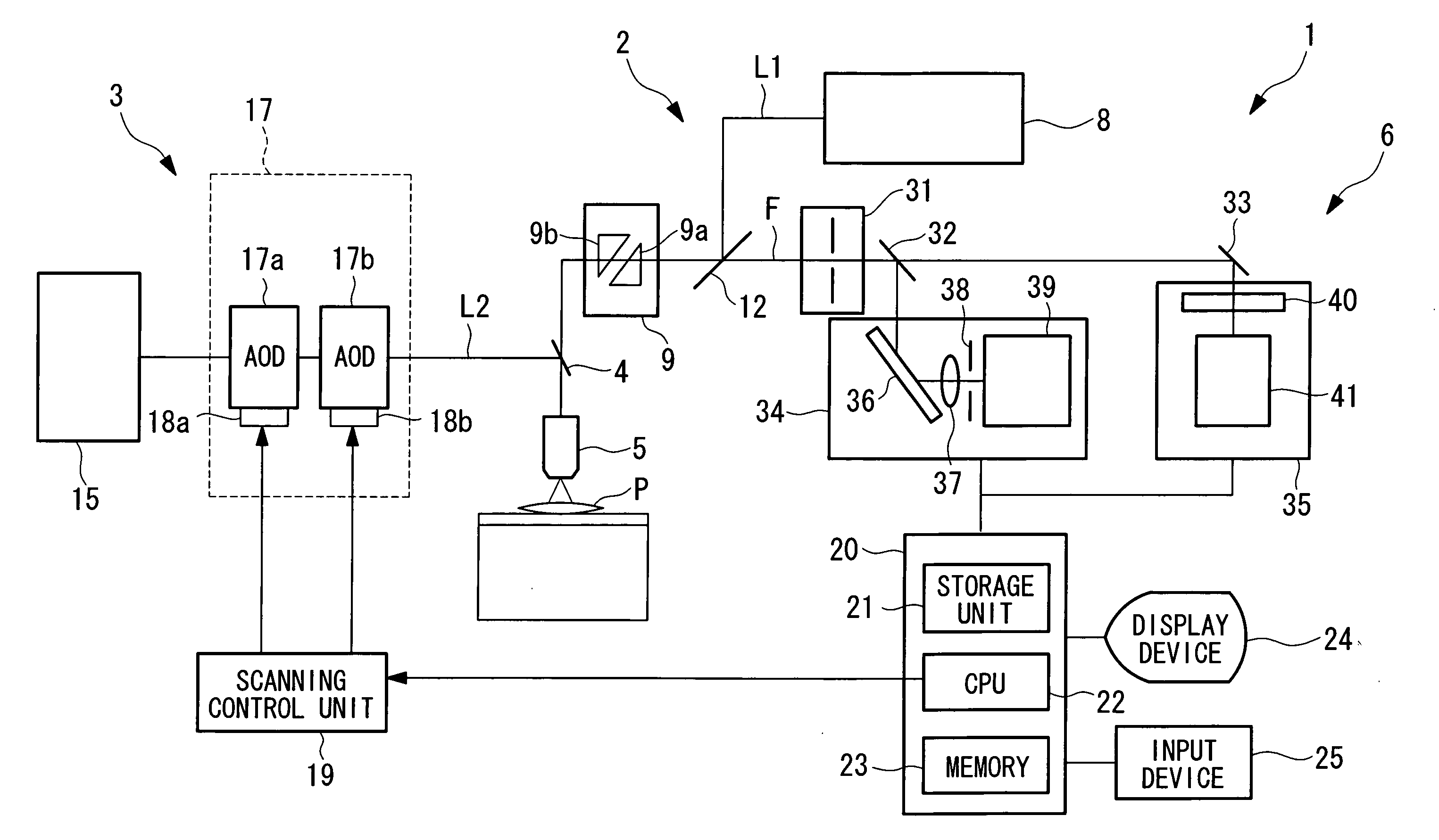
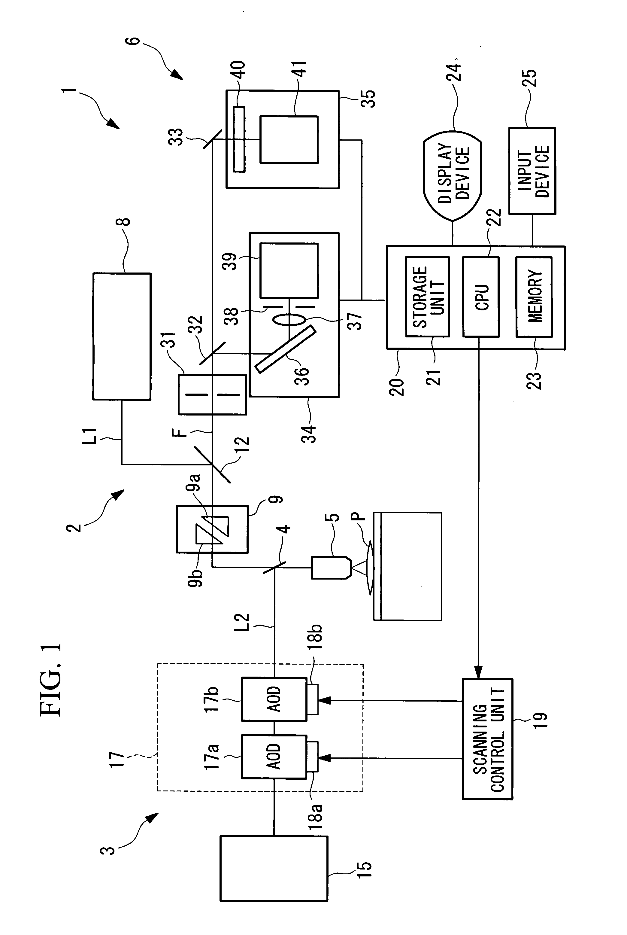
[0060]Referring to FIG. 1, a laser scanning microscope according to the first embodiment is a laser scanning confocal microscope. As shown in FIG. 1, optical parts such as various lenses and a pinhole are omitted for the purpose of a brief description.
[0061]Referring to FIG. 1, a laser scanning microscope 1 according to the first embodiment of the present invention comprises: a scanning optical system 2 for observation that performs scanning with a laser beam L1 for observation; a scanning optical system 3 for stimulation that performs scanning of a laser beam L2 for stimulation; a dichroic mirror 4 that combines waves of the laser beam L1 for observation and the laser beam L2 for stimulation; an objective lens 5 that collects the wave-combined laser beam L1 for observation and the laser beam L2 for stimulation, emits the collected the laser beam L1 for observation and the laser beam L2 for stimulation to a sample P, condenses fluorescent light F generated by exciting a fluorescent ...
second embodiment
[0128]Next, a description will be given of a laser scanning microscope according to the second embodiment of the present invention.
[0129]The laser scanning microscope according to the second embodiment is different from that according to the first embodiment in that the CPU 22 also controls the amplitude of the high-frequency signals applied to the vibrators 18a and 18b.
[0130]Hereinbelow, the common points to those according to the first embodiment with respect to the laser scanning microscope according to the second embodiment will not described, and only different points will be described.
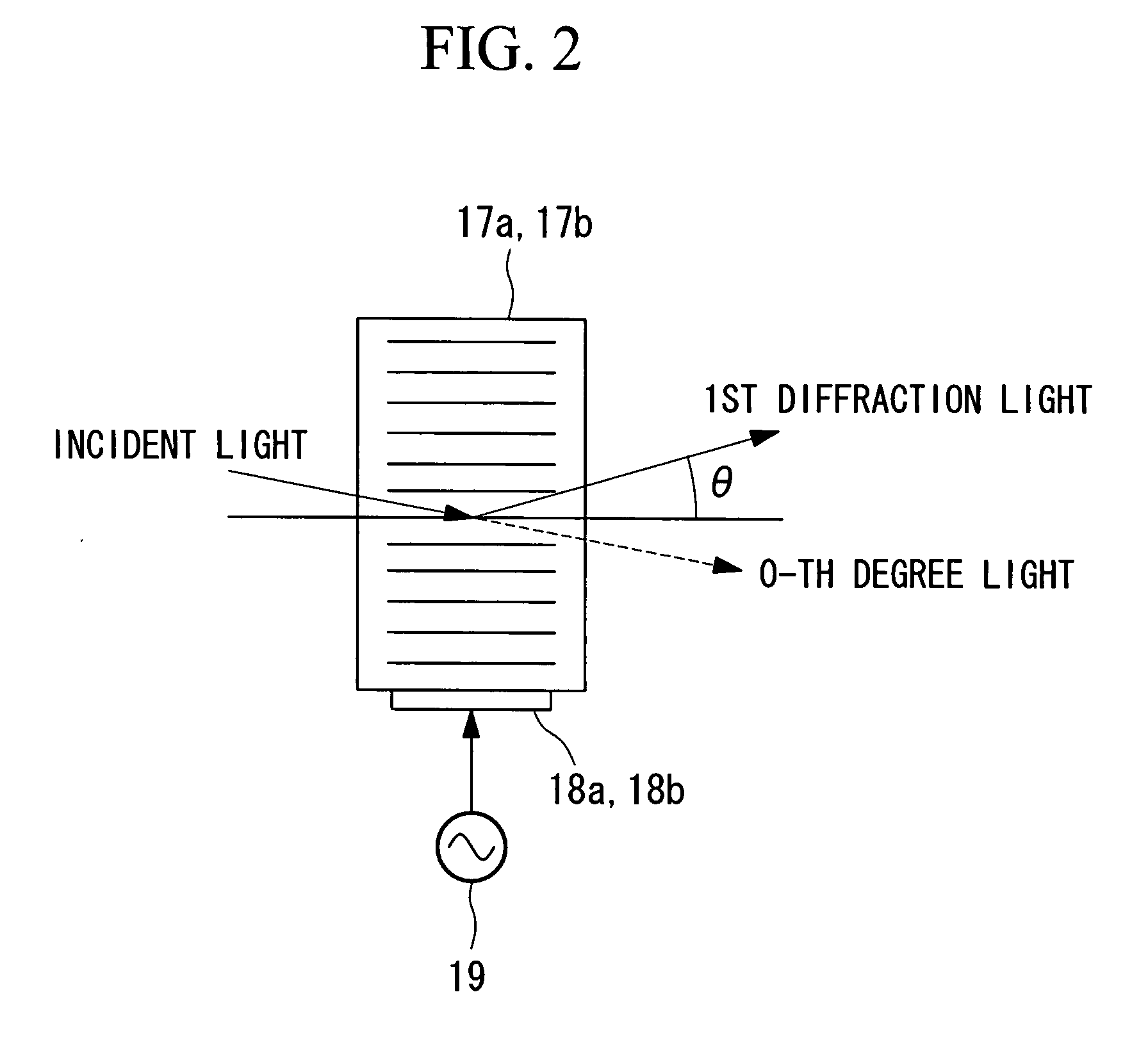
[0131]Referring to FIG. 1, the acoustooptic devices 17a and 17b used for the second scanner 17 have the feature that the intensity of the laser beam L2 for stimulation after the diffraction, i.e., to be emitted is varied depending on the frequency band of the high-frequency signals applied to the vibrators 18a and 18b. Herein, there is a proportional relationship between the intensity of the las...
third embodiment
[0143]Next, a description will be given of a laser scanning microscope according to the third embodiment of the present invention.
[0144]Unlike the laser scanning microscope 1 according to the first embodiment, a laser scanning microscope according to the third embodiment has a galvanic mirror 51 that is mechanically vibrated for light deflection as shown in FIG. 16, in place of the second acoustooptic device 17b.
[0145]The galvanic mirror 51 scans the fluorescent image in the vertical direction with the laser beam L2 for stimulation that position-adjusts the fluorescent image in the horizontal direction with the first acoustooptic device 17a.
[0146]For example, with the laser scanning microscope, the laser beam L2 for stimulation emitted from the laser beam source 15 for stimulation are set as the laser beam L2 for stimulation with the one-dimensional distribution in the horizontal direction by the first acoustooptic device 17a, and are guided to the galvanic mirror 51. The galvanic...
PUM
 Abstract
Description
Claims
Application Information
 - R&D
- Intellectual Property
- Life Sciences
- Materials
- Tech Scout
- Unparalleled Data Quality
- Higher Quality Content
- 60% Fewer Hallucinations
Browse by: Latest US Patents, China's latest patents, Technical Efficacy Thesaurus, Application Domain, Technology Topic, Popular Technical Reports.
© 2025 PatSnap. All rights reserved.Legal|Privacy policy|Modern Slavery Act Transparency Statement|Sitemap|About US| Contact US: help@patsnap.com


