System and method for a power system micro grid

a power system and micro-grid technology, applied in the field of electric power systems, can solve the problems of difficult to build large power generation facilities and their associated high voltage, difficult to procure bulk power transmission line systems, and difficult to sit and be expensive, and achieve the effect of greater reliability

Active Publication Date: 2007-11-29
RHOMBUS ENERGY SOLUTIONS
View PDF22 Cites 42 Cited by
  • Summary
  • Abstract
  • Description
  • Claims
  • Application Information

AI Technical Summary

Benefits of technology

[0019]FIG. 3 is a block diagram of an alternative embodiment of a mobile micro grid that provides for a greater degree of reliability in the connection of the secondary converter module to the AC power system.

Problems solved by technology

However, it is increasingly difficult to build large power generation facilities and their associated high voltage, bulk power transmission line systems.
For example, environmental pollution issues have made siting more difficult and very expensive, particularly when coal, gas, or hydro resources are located on remote, scenic public lands.
Right of way for siting the high voltage, bulk power transmission line systems has become very difficult to procure.
Because of the wide variety of available resources used by smaller power sources, and because of the large number of manufacturers and vendors, there is relatively little uniformity in the design of the smaller power sources and / or their associated equipment.
Further, there is little uniformity in the output capacities, voltages and / or frequencies.
Electrically coupling a plurality of small power sources at a common location presents a variety of unique problems.
This interconnection equipment is very expensive.
And, in many instances, the interconnection equipment is difficult and costly to install.
For example, in the event of civil disorder, a natural disaster or marshal law event, the existing power supply may be disrupted.
Repairing and restoring the damaged power system may take a very long time.
Although some types of power sources are portable, it is problematic that interconnection facilities for connecting the mobile power sources to the power system will be readily available, and available in the most desirable locations.
A fault or failure of a component in one small power source, or its associated equipment, may cause the voltage to collapse to zero volts or near zero volts until protective equipment isolates the faulted component.
If the voltage fluctuation is sufficiently severe, some or all of the other small power sources may be forced off line.

Method used


Image

  • System and method for a power system micro grid
  • System and method for a power system micro grid
  • System and method for a power system micro grid

Examples


Embodiment Construction

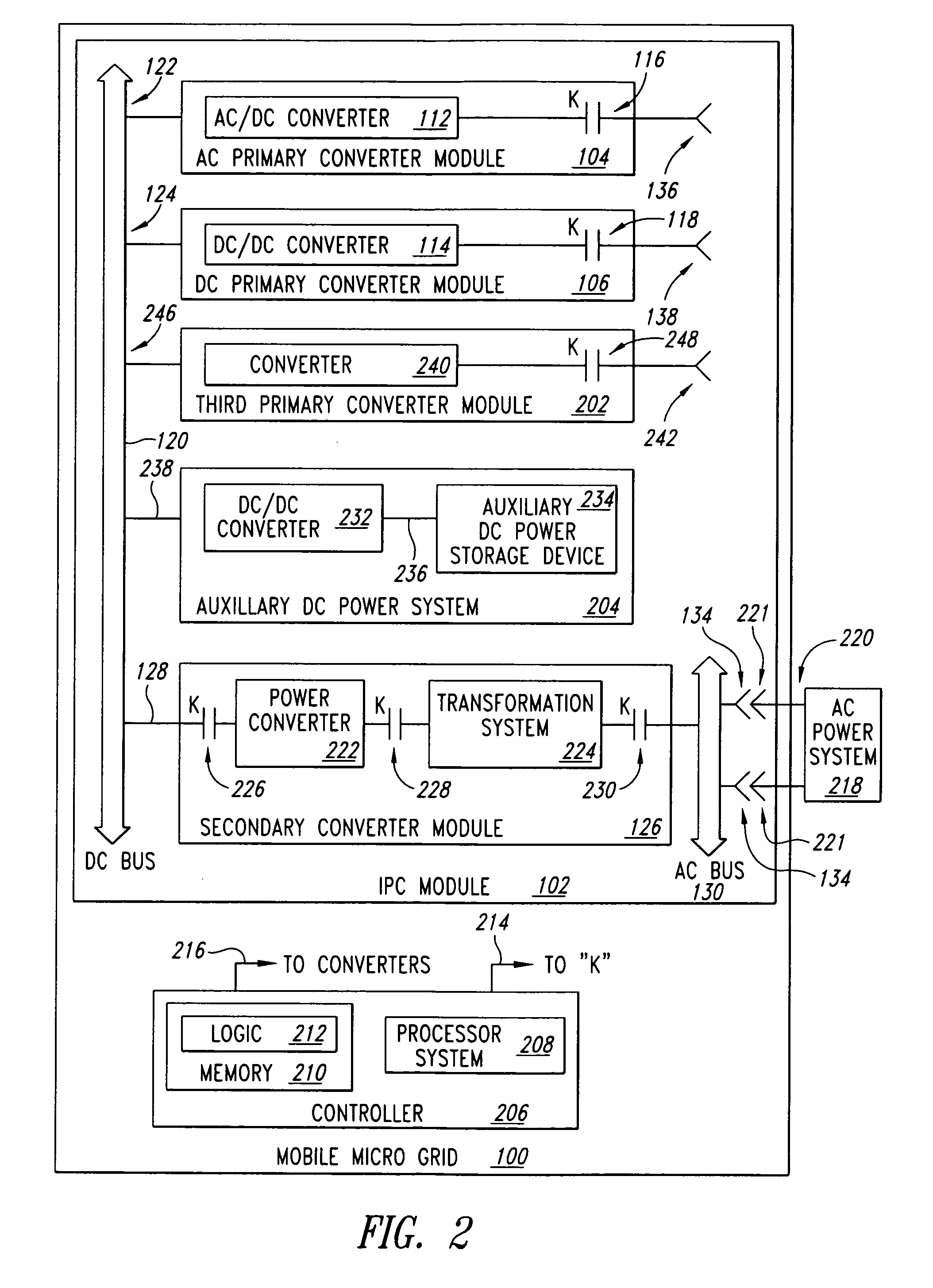
[0030]In the following description, certain specific details are set forth in order to provide a thorough understanding of various embodiments. However, one skilled in the art will understand that the invention may be practiced without these details. In other instances, well-known structures associated with power converters, transformers, contactors, relays, circuit breakers, controllers and / or gate drives have not been shown or described in detail to avoid unnecessarily obscuring descriptions of the embodiments.

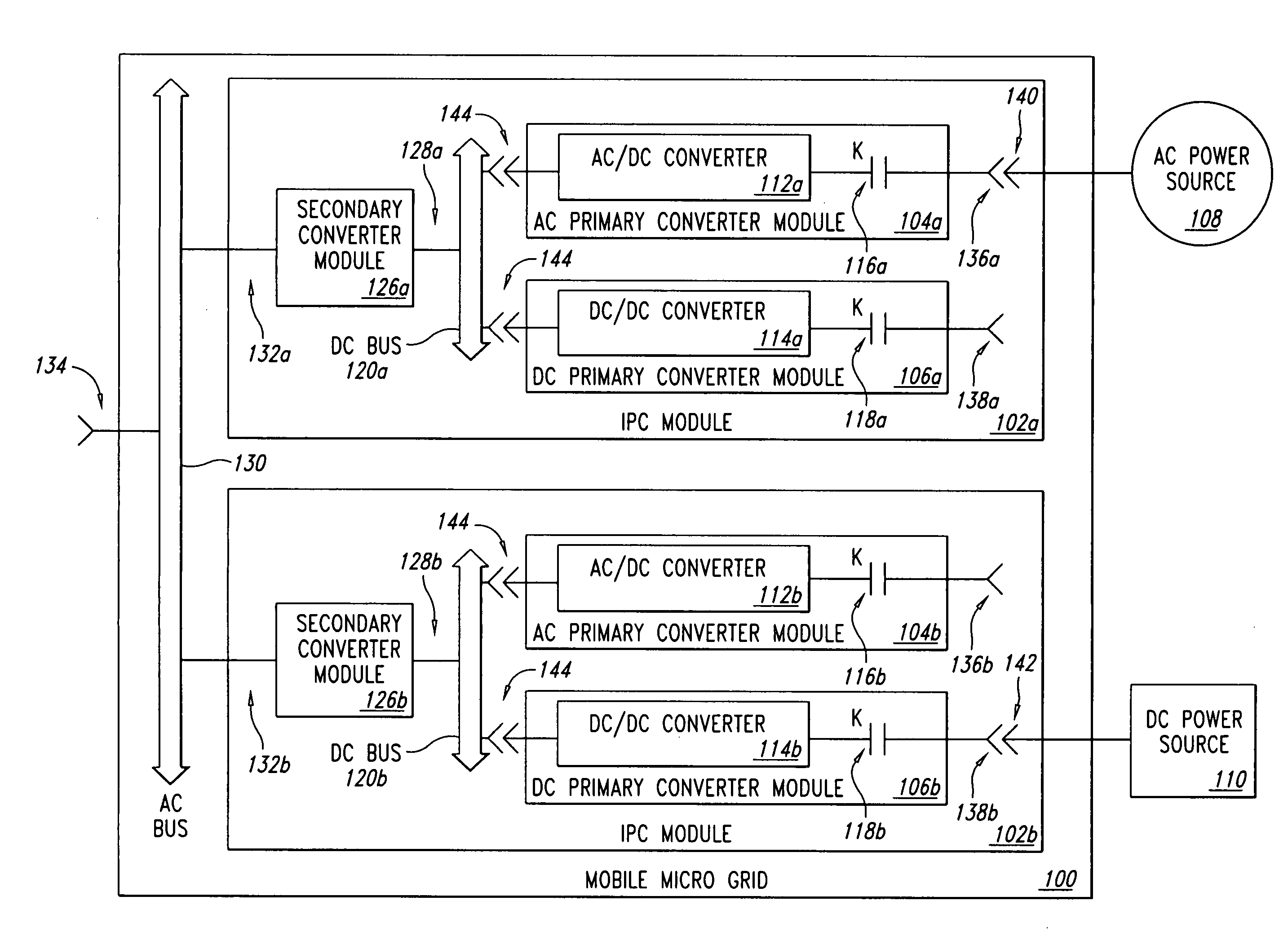
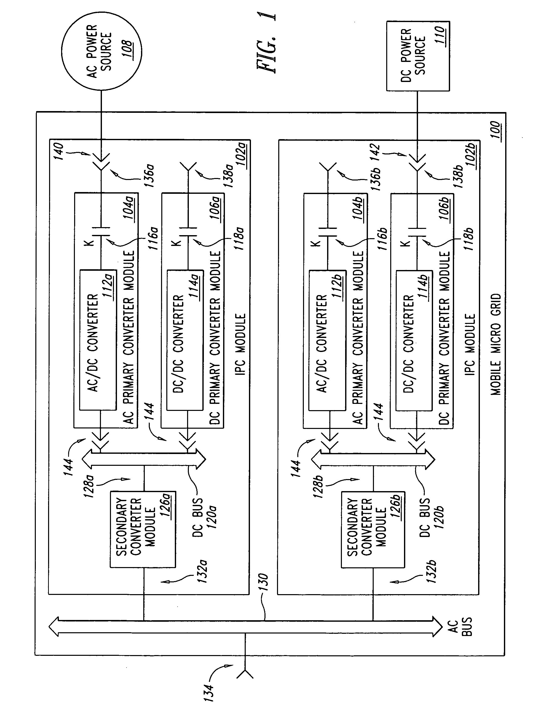
[0031]Furthermore, for convenience, reference numerals may be followed by letter indices to indicate a specific referenced location on a Figure. For example, reference numerals for the input power control (IPC) modules 102a, 102b refer to the upper and lower modules, respectively, illustrated in FIG. 1. General references to embodiments of an IPC module employ the reference numeral “102” without the additional letter indicia.

[0032]Unless the context requires otherwise, throu...


PUM


Abstract

A system and method for transferring power from power sources to an AC power system are disclosed. Briefly described, one embodiment electrically couples an external AC power source to a first input power control (IPC) module that is rated at a first AC input power capacity and that is rated at a first direct current (DC ) input power capacity, operates the first IPC module up to the first AC input power capacity in response to receiving AC power from an external AC power source, electrically couples an external DC power source to a second IPC module that is rated at a second AC input power capacity and that is rated at a second DC input power capacity, and operates the second IPC module up to the second DC input power capacity in response to receiving DC power from an external DC power source.

Description

BACKGROUND OF THE INVENTION[0001]1. Field of the Invention[0002]This disclosure generally relates to electrical power systems, and more particularly to power system architectures suitable for coupling generation resources to an electric grid via a common device.[0003]2. Description of the Related Art[0004]Traditionally, electric power is generated in large amounts at remote, large capacity generation stations. Typically, such large power stations are located close to an energy source and accordingly, are remote from the end users who consume the electric power. To minimize costs associated with the transmission of the generated electrical power to the end users, voltage of the generated electrical power is stepped up to a relatively high voltage for transmission over a high-voltage transmission system or grid. Voltage of the received electric power is then stepped down to a voltage that is useable by the end user, such as 240 volts (v) or 120 v.[0005]However, it is increasingly diff...

Claims


Application Information

Patent Timeline
Patent Type & Authority Applications(United States)
IPC IPC(8): H02J1/12
CPCH02J3/04H02J4/00H02J3/38
Inventor WANG, KON-KING M.HARMON, KENT M.
Owner RHOMBUS ENERGY SOLUTIONS
Why Eureka
Try Eureka