Optical disc drive

Inactive Publication Date: 2007-11-29
HITACHI-LG DATA STORAGE +1
View PDF7 Cites 11 Cited by
  • Summary
  • Abstract
  • Description
  • Claims
  • Application Information

AI Technical Summary

Benefits of technology

[0008]In accordance with the present invention, it is possible

Problems solved by technology

With a high-density optical disc, although numerical aperture is increased as a means for improving the recording density, it becomes impossible to ignore an effect of spherical aberrations caused by a disc cover layer thickness error.
Howeve

Method used


Image

  • Optical disc drive
  • Optical disc drive
  • Optical disc drive

Examples


embodiment 1

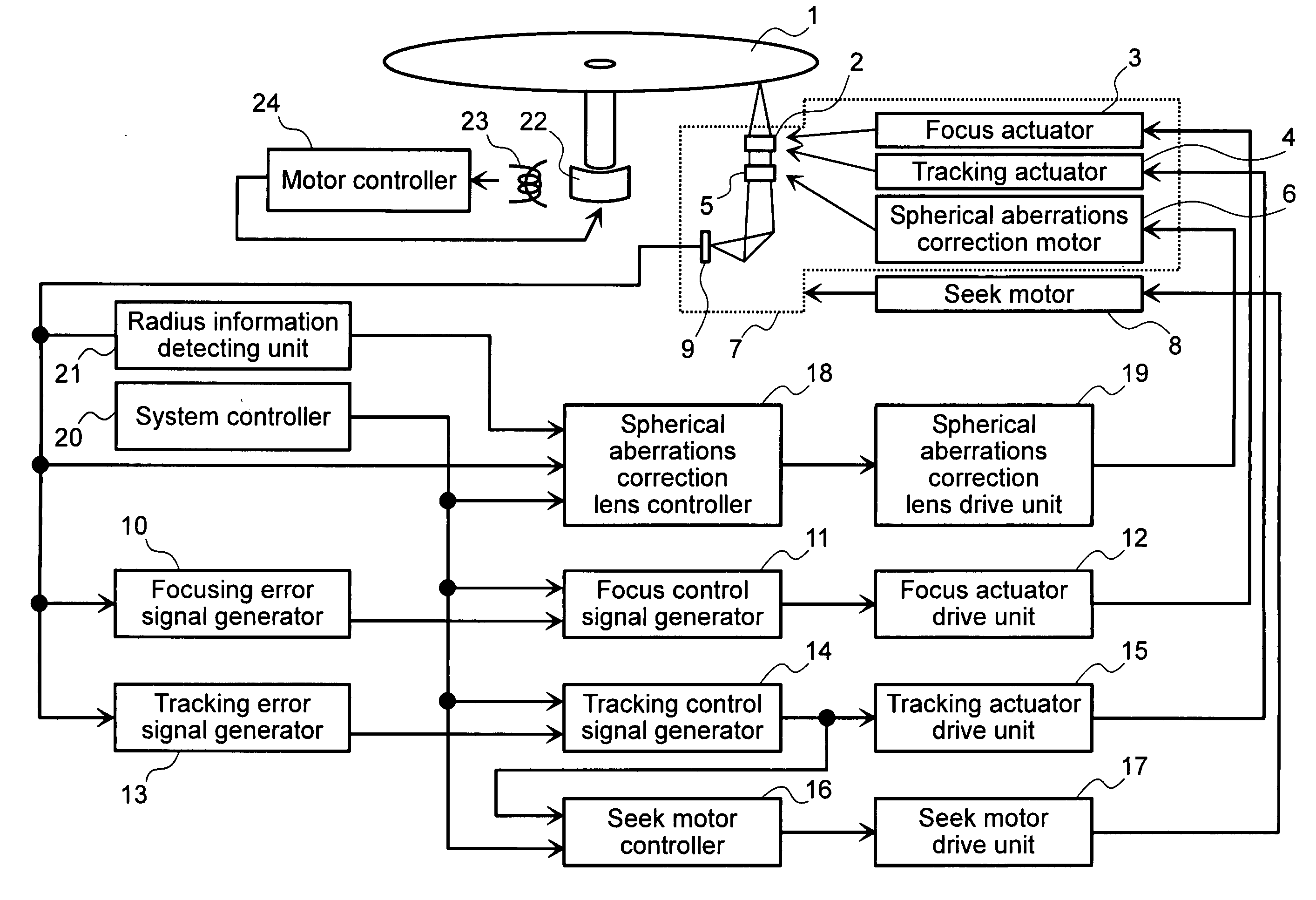
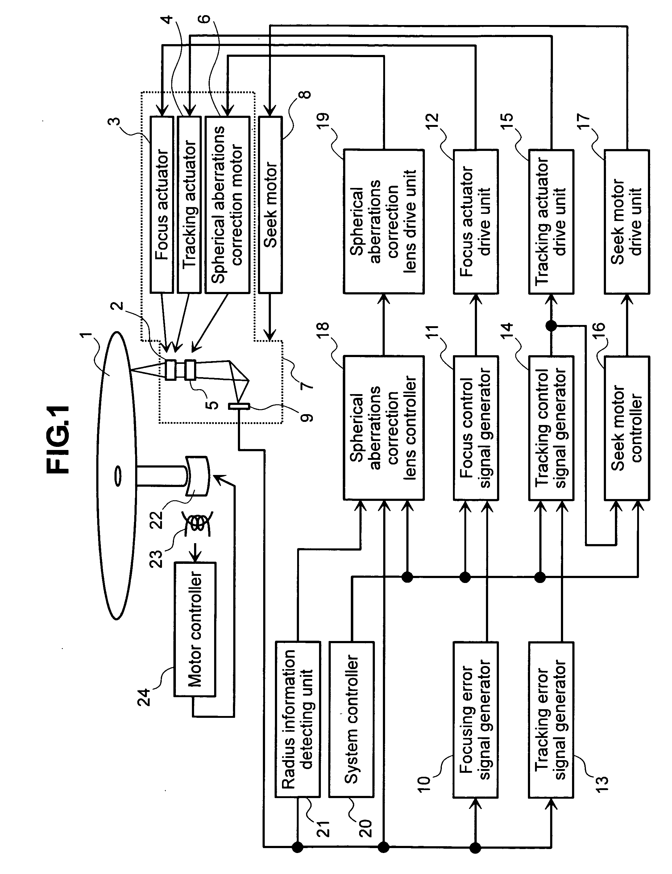
[0018]First, a configuration of an optical disc drive of the present embodiment will be described below with reference to FIG. 1.

[0019]Referring to FIG. 1, the optical disc drive includes a disc 1, an objective lens 2, a focus actuator 3, a tracking actuator 4, a spherical aberrations correction lens 5, and a spherical aberrations correction motor 6. The focus actuator 3 drives the objective lens 2 in the rotating axis direction of the disc 1. The tracking actuator 4 drives the objective lens 2 in the radial direction of the disc 1. The spherical aberrations correction motor 6 drives the spherical aberrations correction lens 5 in the optical axis direction. Further, the optical disc drive includes an optical pickup unit 7, a seek motor 8, a detector 9, a focusing error signal generator 10, a focus control signal generator 11, and a focus actuator drive unit 12. The optical pickup unit 7 includes the objective lens 2 and the spherical aberrations correction lens 5. The seek motor 8 d...


PUM


Abstract

With a high-density optical disc drive, although it is necessary to correct spherical aberrations which depend on a disc substrate thickness error, operation of an aberrations correction element takes time and therefore easy correction according to a disc radius degrades the operability of the apparatus.
The present invention comprises an optical pickup unit including an objective lens and an aberrations correction lens, a focus actuator, a tracking actuator, a aberrations correction motor, a seek motor, an aberrations correction lens control module, a radius information detecting module, and a system control module.

Description

BACKGROUND OF THE INVENTION[0001]The present invention relates to an optical disc drive.[0002]A background art of the present technical field is disclosed, for example, in Japanese Patent Laid-open No. 2005-108334. The above-mentioned patent gazette describes “providing an apparatus which corrects spherical aberrations caused by a difference between discs” as an object and “performing writing or reading by controlling a spherical aberrations control mechanism based on control signal data by radius position stored in a storage means” as a solving means.SUMMARY OF THE INVENTION[0003]With a high-density optical disc, although numerical aperture is increased as a means for improving the recording density, it becomes impossible to ignore an effect of spherical aberrations caused by a disc cover layer thickness error. The disc cover layer thickness means a layer between a disc surface and an information side or a space layer between information sides of a multilayer disc. Therefore, contr...

Claims


Application Information

Patent Timeline
IPC IPC(8): G11B21/10
CPCG11B7/0948G11B7/13927G11B7/1378
Inventor IMAGAWA, SEIJI
Owner HITACHI-LG DATA STORAGE
Why Eureka
Try Eureka