Enhanced Underwater Imaging

Inactive Publication Date: 2007-11-29
TECHNION RES & DEV FOUND LTD
View PDF5 Cites 22 Cited by
  • Summary
  • Abstract
  • Description
  • Claims
  • Application Information

AI Technical Summary

Benefits of technology

[0008] It is a purpose of the present invention to provide

Problems solved by technology

Underwater vision is plagued by poor visibility conditions.
Direct employment of most computer vision methods (e.g., those based on stereo triangulation or on structure from motion) underwater is difficult.
This is due to the particularly challenging environmental conditions, which complicate image matching and analysis.
What makes underwater imaging so problematic?
Since they do not model the spatially varying distance dependencies, traditional methods are of limited utility in countering visibility problems.
A significant problem associated with this is the falloff of scene irradiance with the distance from the strobe.
Yet, the range of such syst

Method used


Image

  • Enhanced Underwater Imaging
  • Enhanced Underwater Imaging
  • Enhanced Underwater Imaging

Examples


Example

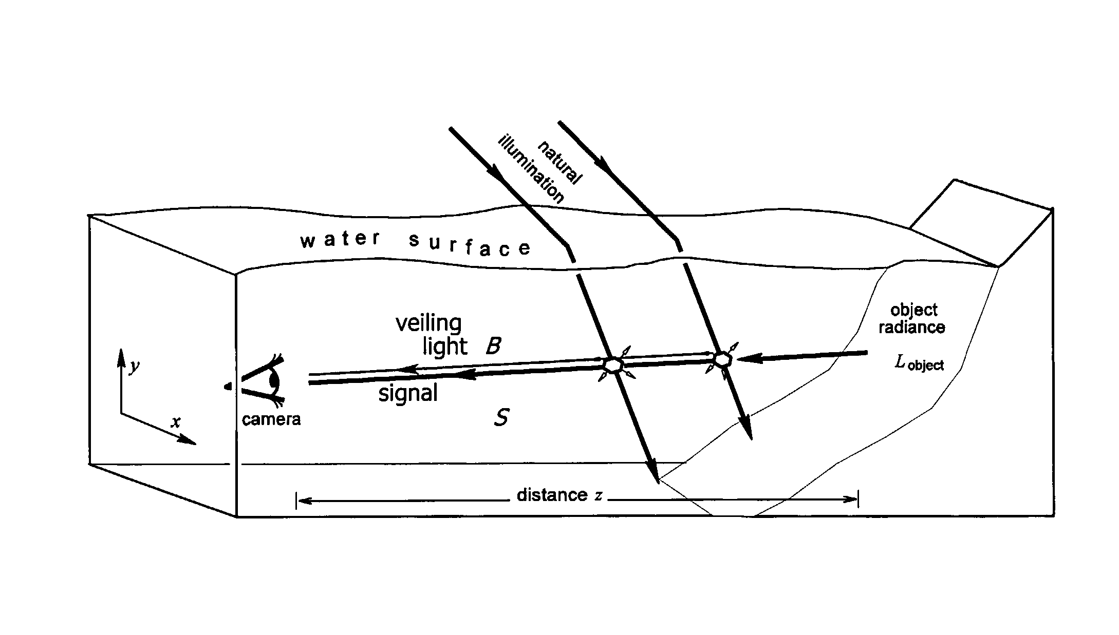
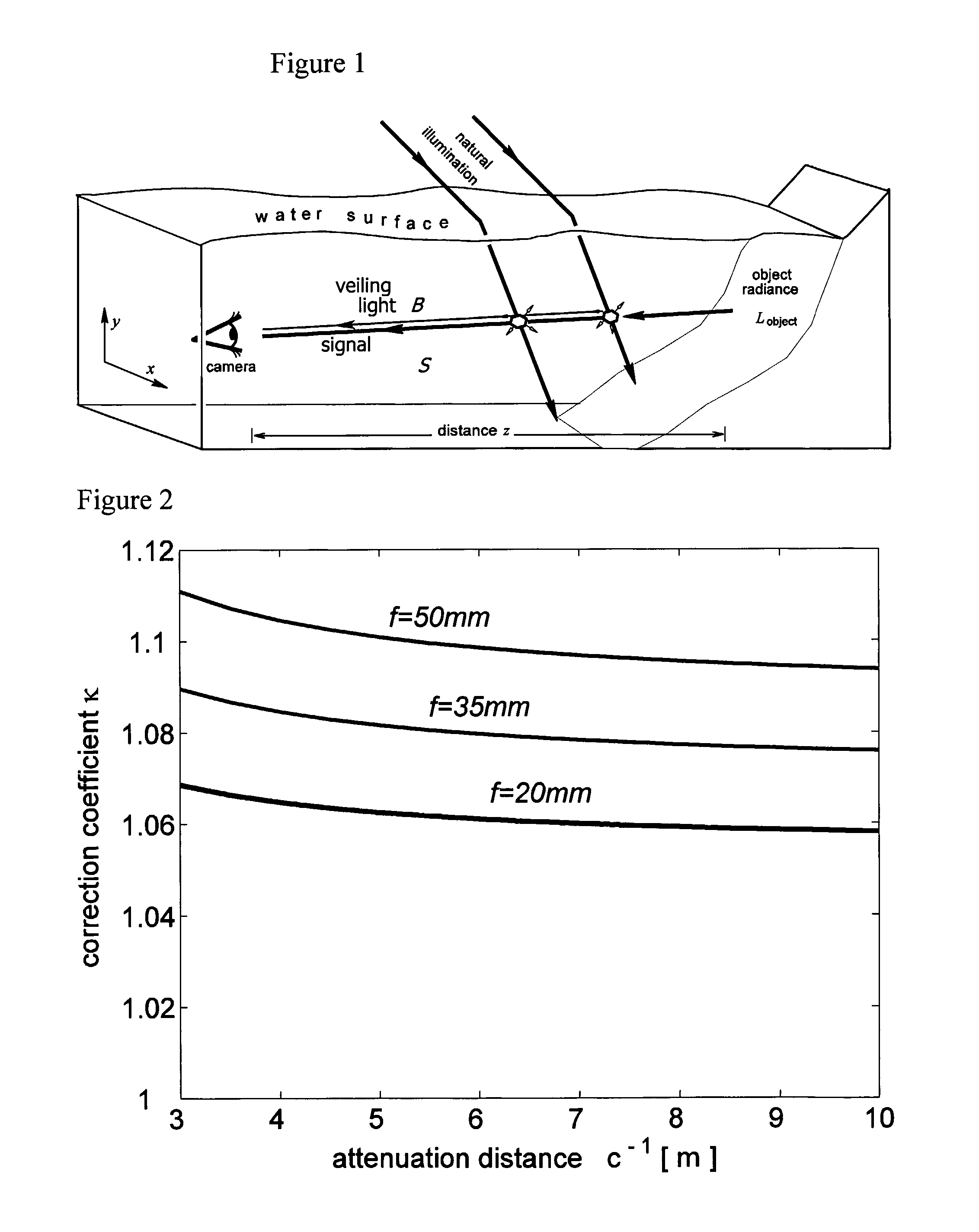
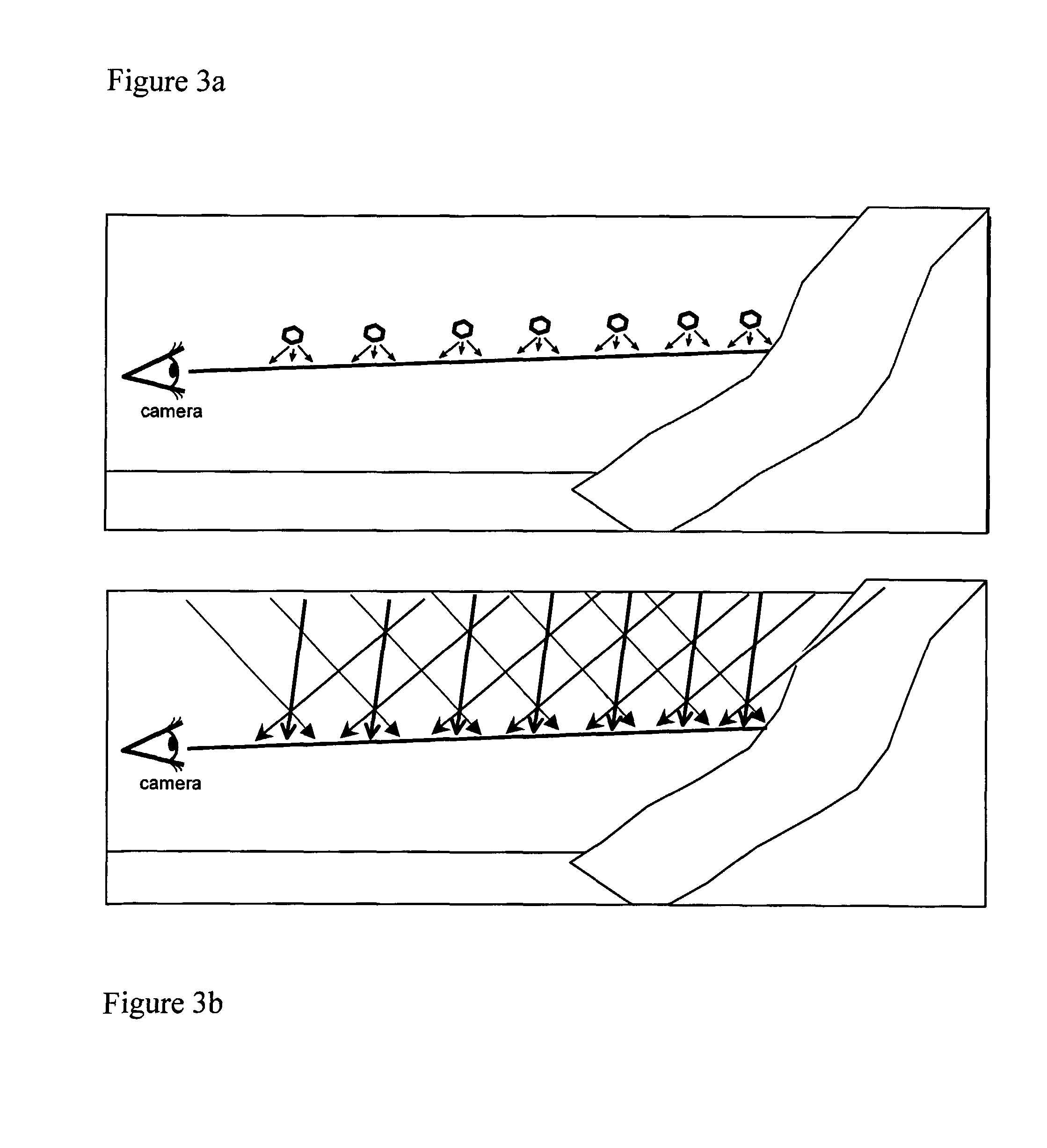
[0040] In this work we develop a physics-based approach for recovery of visibility when imaging underwater scenes, preferably in natural illumination. Since it is based on the models of image formation, the approach automatically accounts for dependencies on object distance, and facilitates retrieving a distance map of the scene as a by-product. The method presented is fast to perform, and according to a preferred embodiment of the present invention relies on raw images taken through different states of a polarizing filter. These raw images have slight photometric differences with respect to one another. The differences serve as initial cues for our algorithm factoring out turbidity effects. It is interesting to note that marine animals too use polarization for improved vision.

[0041] To demonstrate the approach, we have built an underwater polarization imaging system composed of both custom and off-the-shelf components (the considerations for selecting the components are described ...


PUM


Abstract

A method for enhancing underwater imaging affected by image degradation effects, the method comprising: acquiring at least one image of an underwater scene using an imaging device; determining information regarding distances of parts of the scene relative to the imaging device; and reconstructing an image of the underwater scene using a physics-based mathematical model, compensating image characteristics influenced by distance-dependent underwater degradation effects including veiling light, using the information on the distances of parts of the scene from the imaging device, and compensating distance-dependent underwater degradation effects relating to the distance of illumination sources from the scene.

Description

FIELD OF THE INVENTION [0001] The present invention relates to imaging. More particularly, the present invention relates to enhanced underwater imaging. BACKGROUND OF THE INVENTION [0002] Underwater vision is plagued by poor visibility conditions. Direct employment of most computer vision methods (e.g., those based on stereo triangulation or on structure from motion) underwater is difficult. This is due to the particularly challenging environmental conditions, which complicate image matching and analysis. It is important to alleviate these visibility problems, since underwater imaging is widely used in scientific research and technology. Computer vision methods are being used in this mode of imaging for various applications (see, for example, A. Ortiz, M. Simo, and G. Oliver, “A vision system for an underwater cable tracker,” in Machine Vision and Applications, vol. 13, pp. 129-140, 2002) such as mine detection, inspection of underwater power and telecommunication cables, pipelines,...

Claims


Application Information

Patent Timeline
IPC IPC(8): G06K9/40
CPCH04N5/2254G06T5/007G06T5/003H04N23/55
Inventor SCHECHNER, YOAVKARPEL, NIR
Owner TECHNION RES & DEV FOUND LTD
Why Eureka
Try Eureka