Biological reaction method and bioreactor

a bioreactor and biological reaction technology, applied in the field of biological reaction methods and bioreactors, can solve the problems of unstable quality, long reaction time, and general gentleness of biological reaction, and achieve the effects of enduring use, easy immobilization, and long service li

Active Publication Date: 2007-11-29
SHARP KK
View PDF3 Cites 29 Cited by
  • Summary
  • Abstract
  • Description
  • Claims
  • Application Information

AI Technical Summary

Benefits of technology

[0008]An object of the present invention is to provide a biological reaction method and a bioreactor which can reduce biological reaction time and improve quality of biological reactants.

Problems solved by technology

However, the reaction takes long time since the speed of gentle biological reaction is slow.
Therefore, in modern days, there have been many cases where the biological reaction has been not adopted due to the above-stated aspect of time.
As stated above, the biological reaction generally tends to be gentle and therefore slow, and also tends to be unstable in quality.
Specifically, the biological reactions take several hours to several days or, in the case of taking particularly long time, require reaction time of several weeks or more.
However, the biological reaction has been such a problem that offers fewer merits than the chemical reaction in reality.

Method used


Image

  • Biological reaction method and bioreactor
  • Biological reaction method and bioreactor
  • Biological reaction method and bioreactor

Examples


first embodiment

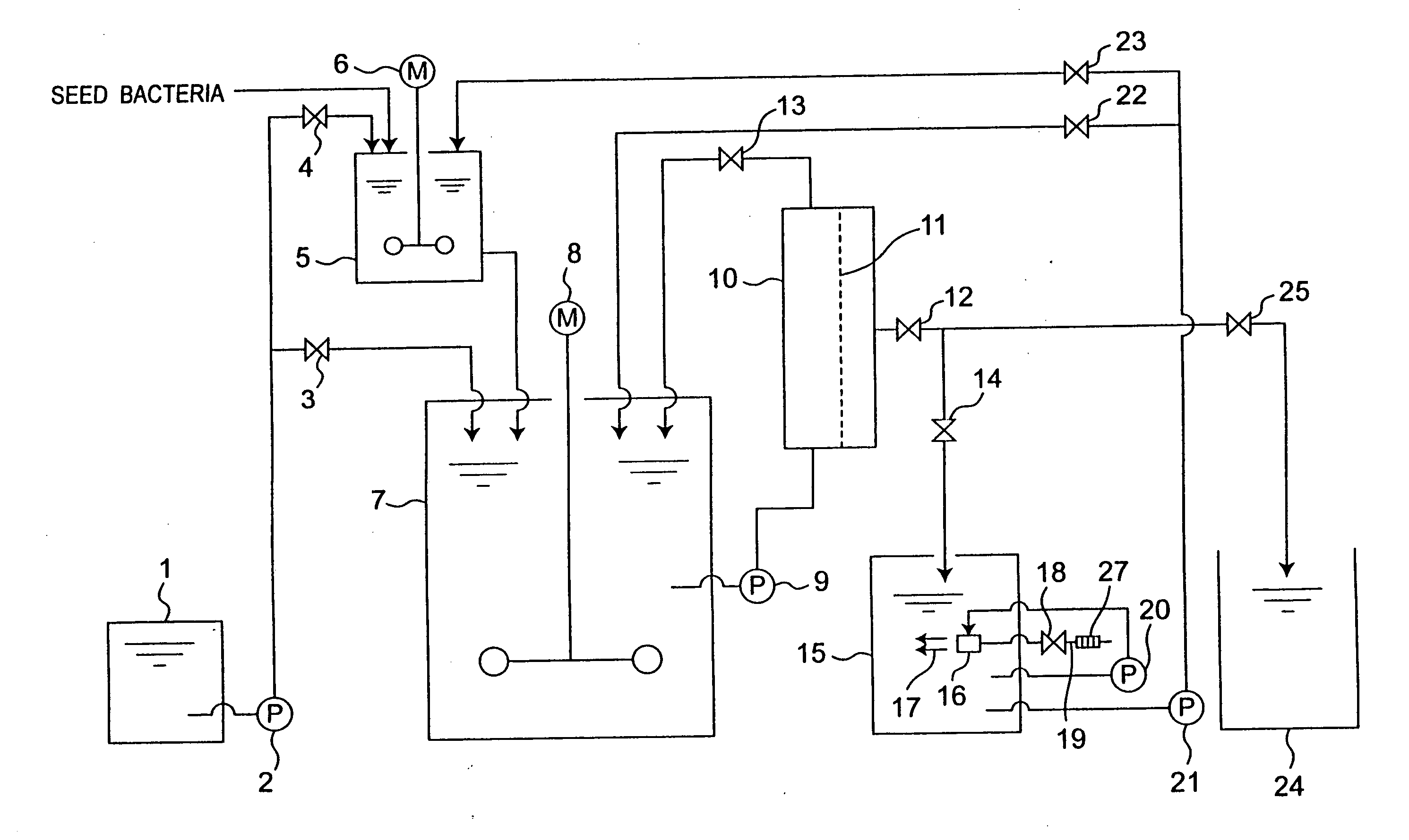
[0055]FIG. 1 is a schematic view showing a bioreactor in a first embodiment of the present invention. This first embodiment is composed of a medium reservoir 1, a seed bacteria cultivation tank 5, a cultivation tank 7 as a biological reaction tank, a bacteria cell filter 10, a micro-nano bubble generation tank 15, and a filtrate reservoir 24.

[0056]In FIG. 1, a nitrogen source, a carbon source, minerals, vitamins and the like are fed to and mixed in the medium reservoir 1. The liquid medium in the medium reservoir 1 is transported to the seed bacteria cultivation tank 5 by a medium reservoir pump 2 when a valve 4 is opened and a valve 3 is closed.

[0057]When cultivation with seed bacteria is completed in the cultivation tank 7 with a result that cultivation of microorganisms is stable, then the valve 3 is put in the opened state while the valve 4 is put in the closed state. The liquid medium is directly transported from the medium reservoir 1 to the cultivation tank 7 by the medium re...

second embodiment

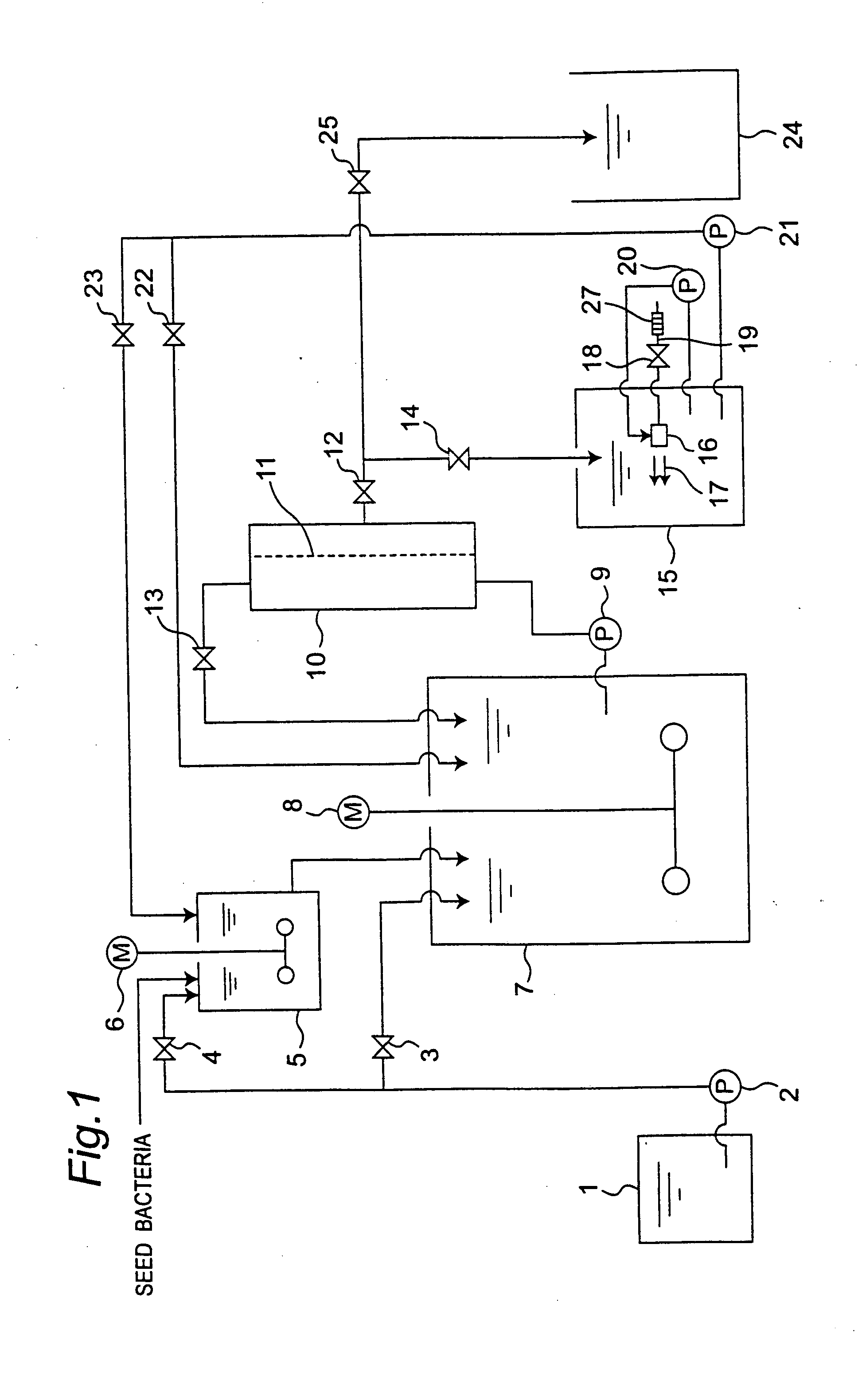
[0077]Next, FIG. 2 is a schematic view showing a bioreactor in a second embodiment of the present invention. The second embodiment is different from the first embodiment shown in FIG. 1 in the points that an air diffusing pipe 43 is placed in the seed bacteria cultivation tank 5, that an air diffusing pipe 44 is placed in the cultivation tank 7, and that a compressor 26, as an air supply section, is connected to the air diffusing pipes 43 and 44 via the disinfection filter 27. In the second embodiment, therefore, component members identical to those in the first embodiment are designated by identical reference numerals, and description will be given of only the portions different from the first embodiment.

[0078]In the second embodiment, the air discharged from the compressor 26 is disinfected by the disinfection filter 27. Thereafter, the air is used for air discharged into the seed bacteria cultivation tank 5 from the air diffusing pipe 43 and air discharged to the cultivation tank...

third embodiment

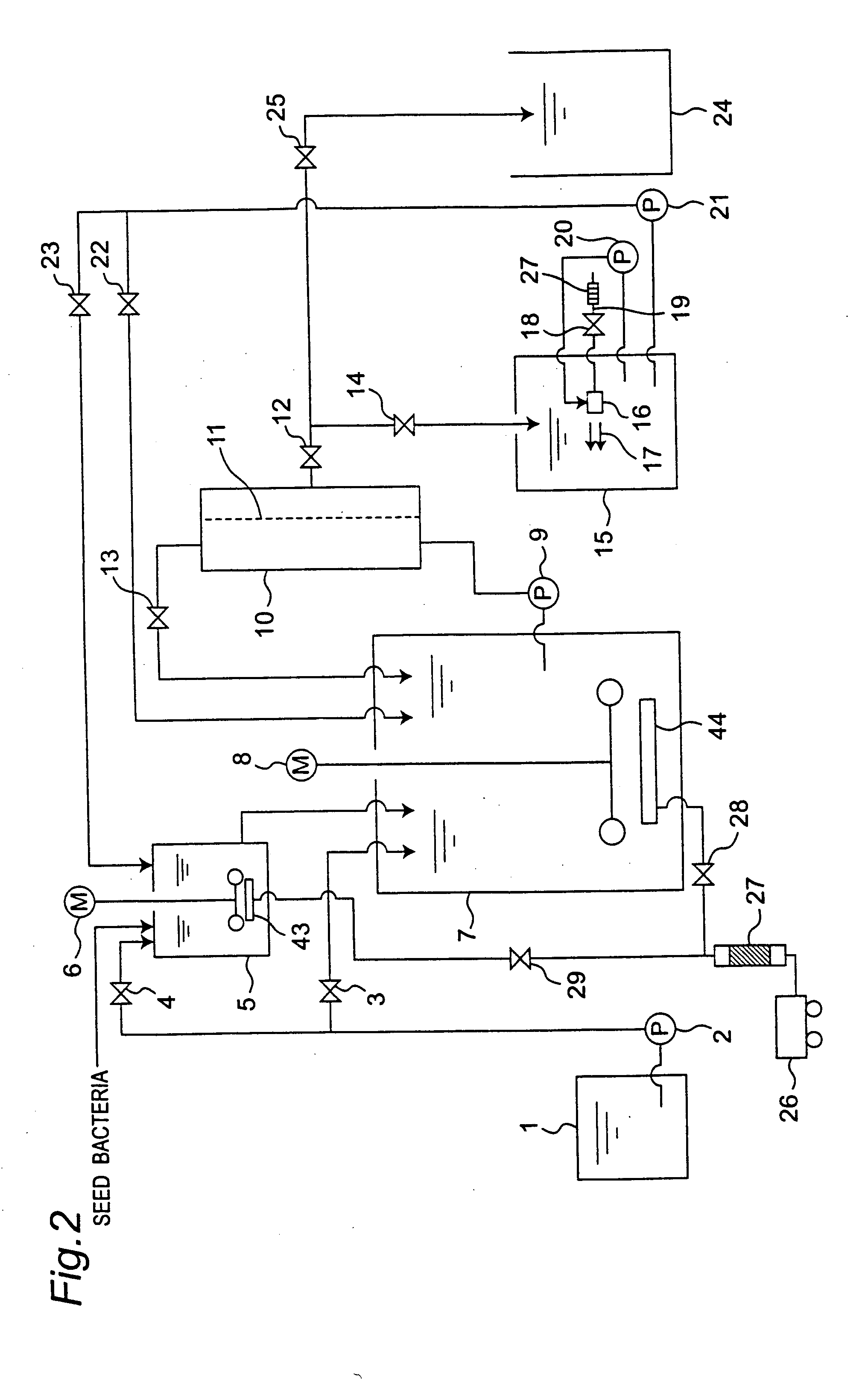
[0081]Next, FIG. 3 is a schematic view showing a bioreactor in a third embodiment of the present invention. The third embodiment is different from the first embodiment shown in FIG. 1 in the point that a medium adjustment tank 31 and a sterilization section 30 below the medium adjustment tank 31 are placed above the medium reservoir 1. Therefore, in the third embodiment, component members identical to those in the first embodiment are designated by identical reference numerals, and description will mainly be given of only the portions different from the first embodiment.

[0082]In the third embodiment, two or more kinds of raw media materials are mixed and adjusted in the medium adjustment tank 31. The two or more kinds of materials mixed in the medium adjustment tank 31 are sterilized in the sterilizing section 30, and thereafter introduced into the medium reservoir 1 by gravity flow.

[0083]In the third embodiment, the mixed materials are sterilized, and therefore, without generating ...


PUM

PropertyMeasurementUnit
diameter sizeaaaaaaaaaa
sizeaaaaaaaaaa
energyaaaaaaaaaa

Abstract

In a bioreactor, a culture solution derived from a cultivation tank is separated into bacteria cells and filtrate by a bacteria cell filter. The filtrate is introduced from the bacteria cell filter into a micro-nano bubble generation tank where micro-nano-bubbles are mixed with the filtrate. The filtrate containing micro-nano-bubbles is returned to the cultivation tank to activate the microorganisms therein, so that a biological reaction time is reduced by the activated microorganisms.

Description

CROSS-REFERENCE TO RELATED APPLICATION[0001]This nonprovisional application claims priority under 35 U.S.C. §119(a) on Patent Application No. 2006-146247 filed in Japan on 26 May 2006, the entire contents of which are incorporated herein by reference.BACKGROUND OF THE INVENTION[0002]The present invention relates to a biological reaction method and a bioreactor, specifically to a biological reaction method and a bioreactor in which micro-nano-bubbles are generated to activate microorganisms in a biological reaction so as to efficiently promote the biological reaction by the activated microorganisms.[0003]Although the biological reaction itself is slow unlike the chemical reaction, the biological reaction is gentle and significant for natural environment since it needs to use neither large energy nor many chemical substances.[0004]However, the reaction takes long time since the speed of gentle biological reaction is slow. Therefore, in modern days, there have been many cases where the...

Claims


Application Information

Patent Timeline
Patent Type & Authority Applications(United States)
IPC IPC(8): C12N1/02C12M1/06C12N1/20C12M1/08
CPCB01F2215/0073C12M27/02C12M37/02C12M29/06C12M29/02B01F2101/44
Inventor YAMASAKI, KAZUYUKISAKATA, KAZUYUKICHUHJOH, KAZUMIKATAOKA, MASAKI
Owner SHARP KK
Why Eureka
Try Eureka