Ipsilateral Approach to Minimally Invasive Ligament Decompression Procedure

a ligament decompression and ipsilateral approach technology, applied in the field of ipsilateral approach to minimally invasive ligament decompression procedure, can solve the problems of back pain, leg pain, weakness and numbness of legs, patients often develop spinal instability, and conservative treatment options often fail

Active Publication Date: 2007-11-29
VERTOS MEDICAL
View PDF99 Cites 83 Cited by
  • Summary
  • Abstract
  • Description
  • Claims
  • Application Information

AI Technical Summary

Benefits of technology

[0019] The present invention provides methods, devices and systems for treating spinal stenosis or other spinal disorders using image guidance in combination with percutaneous techniques. Embodiments of the present approach are referred to as an ipsilateral approach minimally invasive ligament de

Problems solved by technology

The excessive epidural fat compresses the dural sac, nerve roots and blood vessels contained therein and resulting in back, leg pain and weakness and numbness of the legs.
These conservative treatment options frequently fail.
Also, because the spine stabilizing back muscles and ligaments are stripped and detached from the spine during the laminectomy, these patients frequently develop spinal instability post-operatively.
Percutaneous discectomy devices with fluoroscopic guidance have been used successfully to treat disorders of the disc but not to treat spinal stenosis or the ligamentum flavum

Method used


Image

  • Ipsilateral Approach to Minimally Invasive Ligament Decompression Procedure
  • Ipsilateral Approach to Minimally Invasive Ligament Decompression Procedure
  • Ipsilateral Approach to Minimally Invasive Ligament Decompression Procedure

Examples


Embodiment Construction

[0045] The following discussion is directed to various embodiments of the invention. Although one or more of these embodiments may be preferred, the embodiments disclosed should not be interpreted, or otherwise used, as limiting the scope of the disclosure, including the claims. In addition, one skilled in the art will understand that the following description has broad application, and the discussion of any embodiment is meant only to be exemplary of that embodiment, and not intended to intimate that the scope of the disclosure, including the claims, is limited to that embodiment

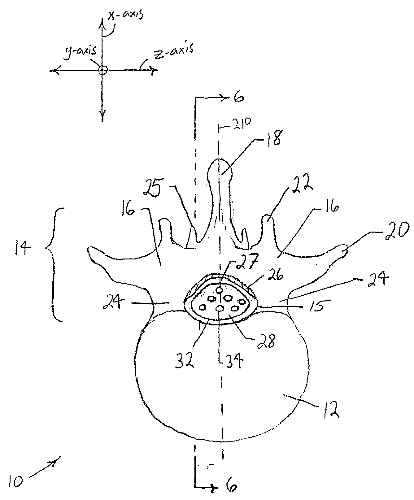
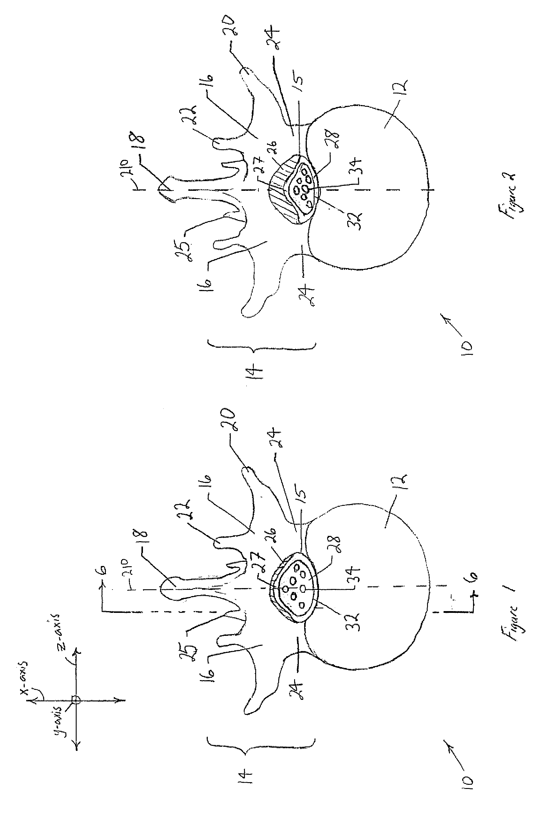
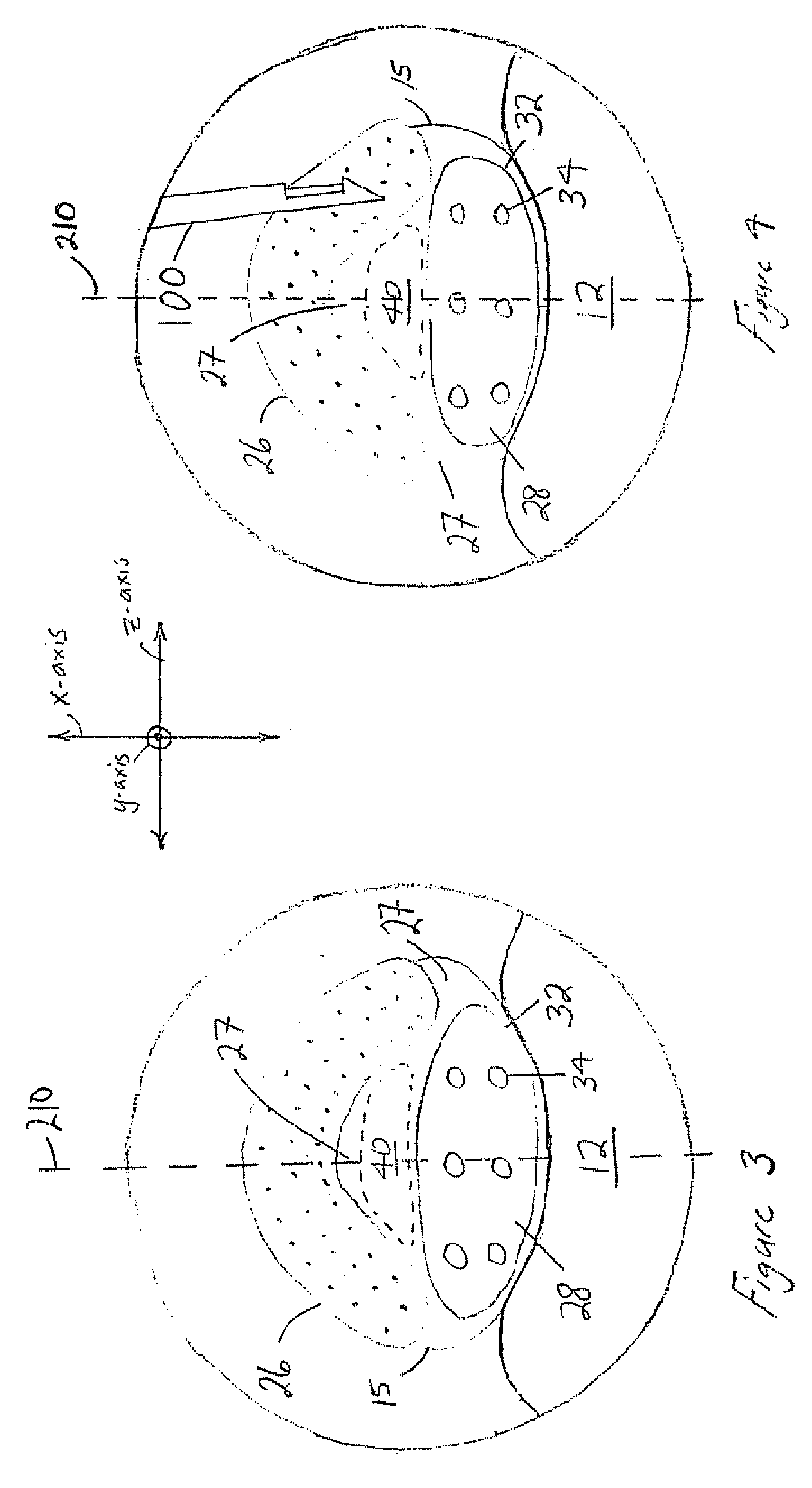
[0046] For purposes of this discussion, the x-, y-, and z-axis are shown in FIGS. 1, 3, 5, 6, and 7 to aid in understanding the descriptions that follow. The x-, y-, and z-axis have been assigned as follows. The x-axis is perpendicular to the longitudinal axis of the vertebral column and perpendicular to the coronal / frontal plane (i.e., x-axis defines anterior vs. posterior relationships). The y-axis runs ...


PUM


Abstract

A method for treating stenosis in a spine of a patient having a median plane, wherein the spine includes a spinal canal having a posterior surface, a dural sac and an epidural space between the posterior surface and dural sac, the location of the stenosis determining a region of interest in the spine. In an embodiment the method comprises the steps of a) generating at least one view of a portion of the spinal canal in the region of interest; b) compressing the dural sac in the region of interest by injecting a fluid to form a safety zone and establish a working zone in the region of interest, the safety zone lying between the working zone and the dural sac; c) percutaneously accessing the epidural space in the region of interest on a first side of the median plane; d) inserting a tissue removal tool into tissue in the working zone on the first side of the median plane; e) using the tissue removal tool to percutaneously reduce the stenosis on the first side of the median plane; and f utilizing the at least one view to position the tissue removal too during at least a part of step d) and at least part of step e)

Description

CROSS-REFERENCE TO RELATED APPLICATIONS [0001] Not Applicable. STATEMENT REGARDING FEDERALLY SPONSORED RESEARCH OR DEVELOPMENT [0002] Not Applicable. BACKGROUND [0003] 1. Field of the Invention [0004] The present invention relates to minimally invasive methods, devices and systems for treating spinal disorders using imaging guidance. This invention also relates to devices used to reduce stenosis and increase the cross-sectional area of the spinal canal available for the spinal cord. This invention also relates to methods, devices, therapies and medications used to treat disorders that involve the epidural space within the spinal canal. [0005] 2. Background of the Invention [0006] The vertebral column (spine, spinal column, backbone) forms the main part of the axial skeleton, provides a strong yet flexible support for the head and body, and protects the spinal cord disposed in the vertebral canal, which is formed within the vertebral column The vertebral column comprises a stack of v...

Claims


Application Information

Patent Timeline
IPC IPC(8): A61B17/00
CPCA61B10/0275A61B17/0218A61B17/064A61B17/221A61B17/320016A61B17/320783A61M5/007A61B2017/0427A61B2017/0437A61B2017/0647A61B2017/22034A61B6/481A61B17/22A61B2017/0412
Inventor SOLSBERG, MURRAY D.SCHOMER, DONALDREEVES, TIMOTHY MARSHALLWAY, BRYCE
Owner VERTOS MEDICAL
Why Eureka
Try Eureka