Railway vehicle head structure

A rail vehicle and locomotive technology, applied in the direction of railway vehicle wheel guards/buffers, buffer cars, railway car bodies, etc., can solve the problems of overall perspective considerations, failure to meet requirements, failure to protect drivers well, etc., to achieve uniformity Stress, improve the effect of collision safety performance

Active Publication Date: 2016-12-21
ZHUZHOU ELECTRIC LOCOMOTIVE CO LTD
View PDF18 Cites 36 Cited by
  • Summary
  • Abstract
  • Description
  • Claims
  • Application Information

AI Technical Summary

Problems solved by technology

[0005] Chinese invention patent application CN201310505736.X, Chinese utility model patent CN201120420346.9, Japanese patent publication number JP2004268694A discloses a modular cab with an anti-climbing energy-absorbing device, and the practical application of Chinese utility model patent CN201410000695.3 The newly disclosed anti-climber of an urban rail driver's cab structure is detachable, but the deformation area of ​​these disclosed cabs is only limited to the front end of the anti-climber mounting plate, and the anti-climber mounting plate is far from the front end of the car body. Short distance, small deformable area, limited energy absorption
Chinese invention patent application CN201310072635.8 discloses the composition of the front end of the train with an anti-climbing energy-absorbing device, including a coupler box at the front end of the traction beam of the car body, a coupler mounting seat arranged at the front end of the traction beam of the car body, and a mounting seat of the anti-climbing energy-absorbing device and anti-climbing energy-absorbing device, but the structure mainly resists the vertical load when the vehicle climbs up through the underframe itself, which makes the underframe structure too complicated and does not consider from the overall point of view, that is, to use the driver's cab frame to improve the vertical load. Carrying capacity
The U.S. invention patent US6561105B2 discloses a driver's cab with an energy-absorbing element above the floor. When two trains collide, the energy-absorbing element will work together with the anti-climbing device, but its longitudinal crush strength cannot be higher than that of the passenger compartment anyway. Therefore, when the longitudinal crush stroke does not increase and the strength of the main structure of the car body remains unchanged, the total amount of collision energy absorbed cannot be effectively improved by setting more energy-absorbing elements alone. Setting energy-absorbing elements will reduce the size of the front window and reduce the driver's field of vision
[0006] In addition, the stainless steel cab structure of the existing B-type urban rail vehicles in China basically cannot meet the 300kN compressive load requirement under the front window.
For example, the stainless steel subway driver's cab car body structure disclosed in Chinese utility model patent 201020677752.9, the steel skeleton under the window is mainly used to support the glass fiber reinforced plastic hood, and the structure is weak, which cannot protect the driver from being hit by obstacles in front of the train during the running of the vehicle.
The aluminum alloy car body disclosed in Chinese utility model patent 201020107739.X considers this working condition, but it is mainly realized by the structural strength of the driver's cab frame itself, without comprehensive consideration of the front-end structure of the chassis, and there is not enough deformation and energy absorption in the front area, security still lacking

Method used


Image

  • Railway vehicle head structure
  • Railway vehicle head structure
  • Railway vehicle head structure

Examples


Embodiment Construction

[0052] The present invention will be described in detail below with reference to the accompanying drawings and examples. It should be noted that, in the case of no conflict, the embodiments of the present invention and the features in the embodiments can be combined with each other. For the convenience of description, if the words "up", "down", "left" and "right" appear in the following, it only means that the directions of up, down, left and right are consistent with the drawings themselves, and do not limit the structure.

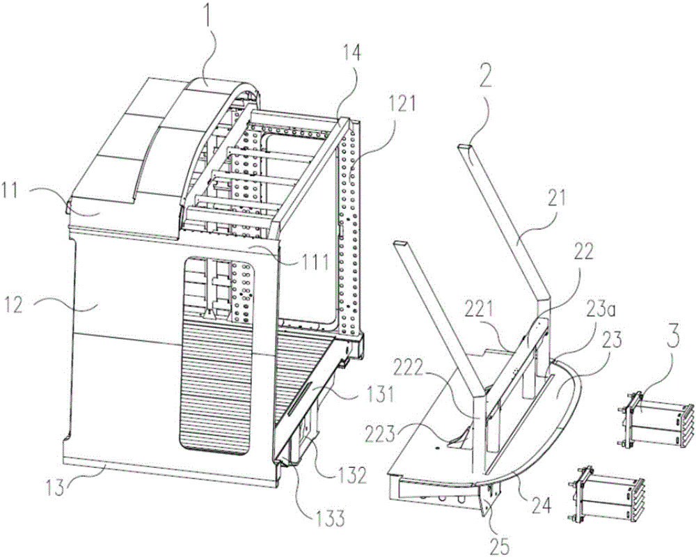
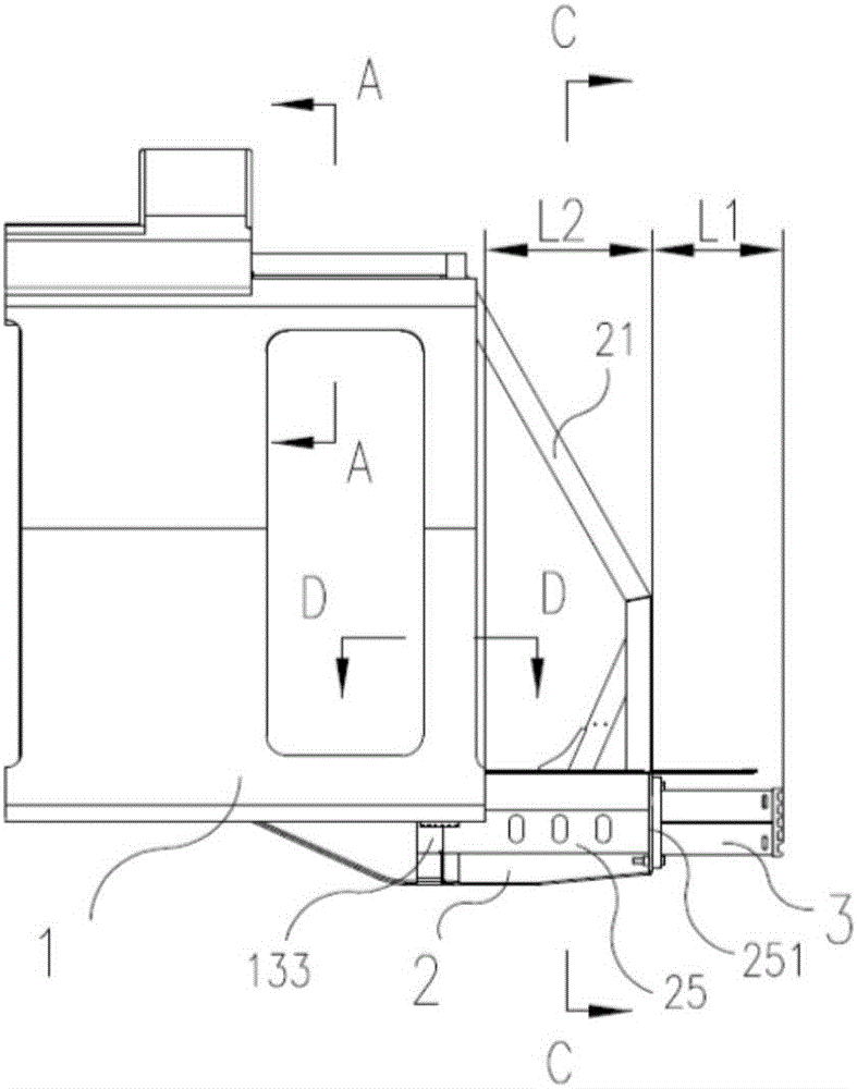
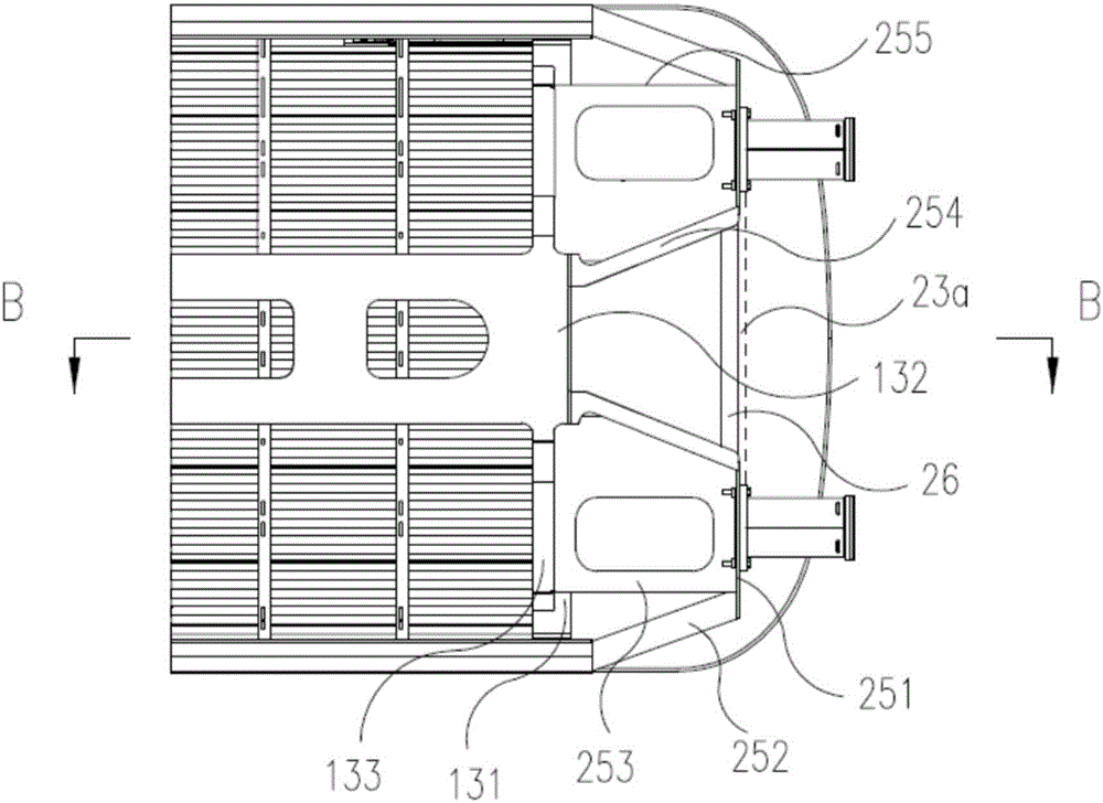
[0053] A rail vehicle head steel structure, such as figure 1 It is shown that the coupler steel structure is mainly composed of the main body structure 1, the front anti-collision structure 2 and the anti-climber 3, and its longitudinal load strength is gradually decreasing, corresponding to the safe area, the difficult deformation area as the secondary deformation area, and the hard-to-deform area as the secondary deformation area. Easy deformation zone...


PUM


Abstract

The invention discloses a railway vehicle head structure. The railway vehicle head structure comprises a vehicle body main structure, a vehicle head anti-collision structure and an anti-creeper. A vehicle head is divided into a safety zone of which the longitudinal load strength is decreased progressively in a gradient mode, a secondary deformation zone and a main deformation zone according to the longitudinal direction of a railway vehicle. The safety zone is the vehicle body main structure and comprises a passenger room zone and a driver seat zone. The secondary deformation zone is a zone from a cab front door to an anti-creeper installation plate and comprises the vehicle head anti-collision structure and an anti-creeper installation structure. The main deformation zone comprises a cab floor located in front of the anti-creeper installation plate and the anti-creeper. A first-stage stopping structure is arranged between the secondary deformation zone and the main deformation zone. A second-stage stopping structure is arranged between the safety zone and the secondary deformation zone. According to the railway vehicle head structure, a vehicle body deforms and absorbs energy in a controllable and orderly mode, and the good safety performance is obtained.

Description

technical field [0001] The invention relates to a rail vehicle front structure, in particular to a vehicle front structure with good collision safety performance, and belongs to the field of rail vehicle body structures. Background technique [0002] At present, energy-absorbing components such as coupler buffers of subway vehicles can only meet the impact of two trains at a relative speed of less than 20km / h. At higher speeds, the coupler system will fail or shear, and the car body will contact and deform due to impact. Drivers cause harm. In order to improve the passive safety performance of railway vehicles, the European Union and the International Association of Railways jointly undertook the European Train Collision Avoidance Project (SAFETRAIN), and spent a lot of money on physical crash tests. The test object was the end structure of the car body deformed in a controlled manner . Subsequently, the European Union promoted the member states to formulate unified collis...

Claims


Application Information

Patent Timeline
Patent Type & Authority Applications(China)
IPC IPC(8): B61D17/00B61F1/00B61F19/04
CPCB61D15/06B61F1/10B61G11/16B61D17/00B61F1/00B61F19/04
Inventor 苏柯李耘茏苏永章王赵华李孟梁王艳谢红兵
Owner ZHUZHOU ELECTRIC LOCOMOTIVE CO LTD
Why Eureka
Try Eureka