Power Switch

Inactive Publication Date: 2007-11-29
INT POWER SWITCH
View PDF11 Cites 94 Cited by
  • Summary
  • Abstract
  • Description
  • Claims
  • Application Information

AI Technical Summary

Benefits of technology

[0084] The belongings may be used in order to define and structure outlets so that it may be possible to obtain a map of the network. This may facilitate the work for a network administrator since he/she can easily overview and manage the system.
[0085] The method may comprise the step of creating a wallet file, pref

Problems solved by technology

The trend of an increasing number of electronic devices makes it very difficult for network administrators to control an entire network and its devices.
However, existing power switches have many drawbacks.
However, they are not able to control the power on/off and/or sequence in an intelligent way.
Furthermore, existing power switches are usually not a part of a bigger control system and is usually not in direct contact with for example a central control unit.
Moreover, existing power switches lack the ability to react independently without receiving instructions from a control unit.
This may result in a very long reaction time, which may decrease the up-time for a server.
J

Method used


Image

  • Power Switch
  • Power Switch
  • Power Switch

Examples


Embodiment Construction

[0176] Description of the Power Distribution Device (PDU)

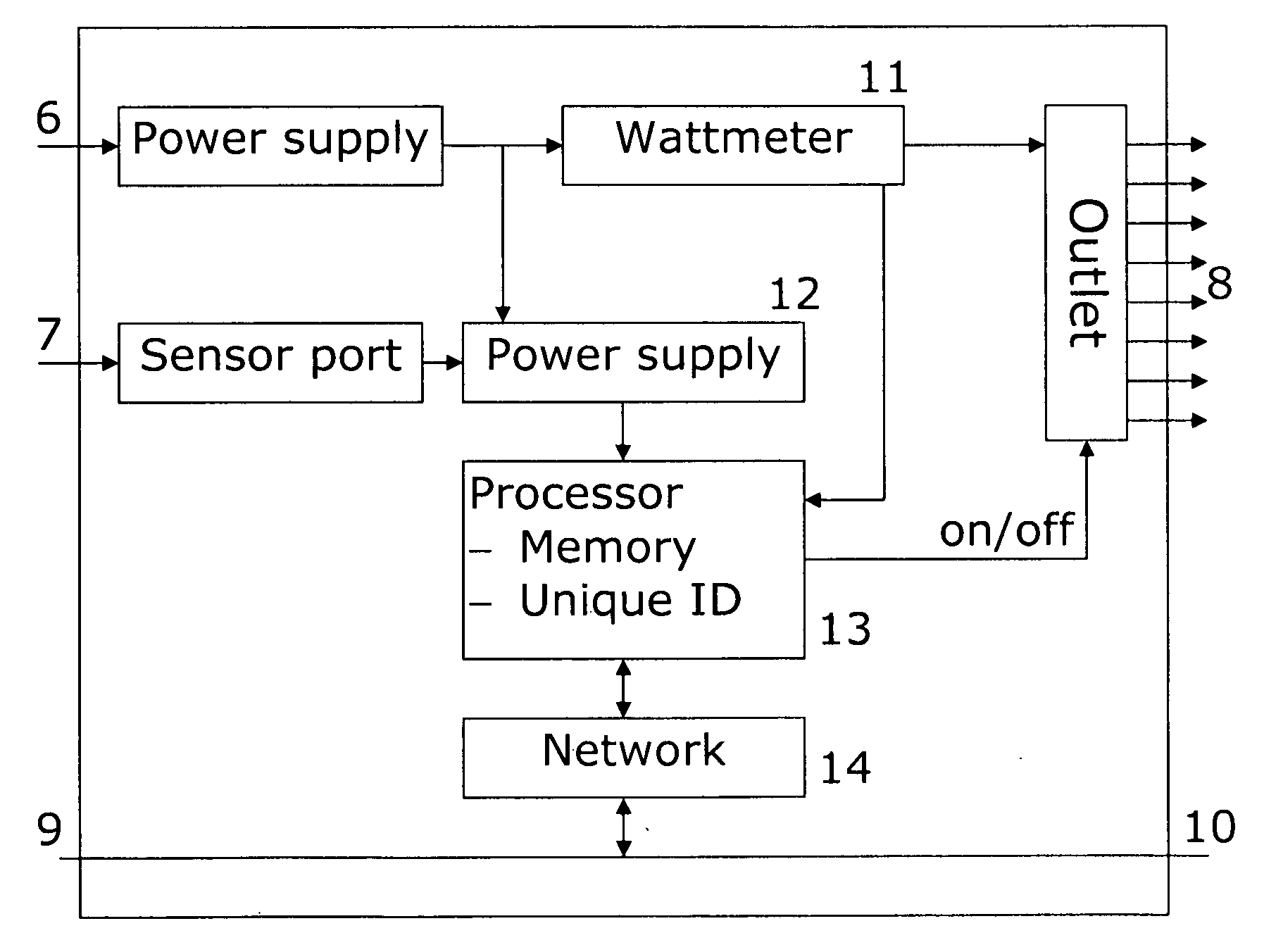
[0177] The power distribution device according to the invention is preferably a combination between a power switch, a computer and a sensor system mounted within the same housing. The PDU is intelligent, as it is able to act on its own and make decisions depending on inputs.

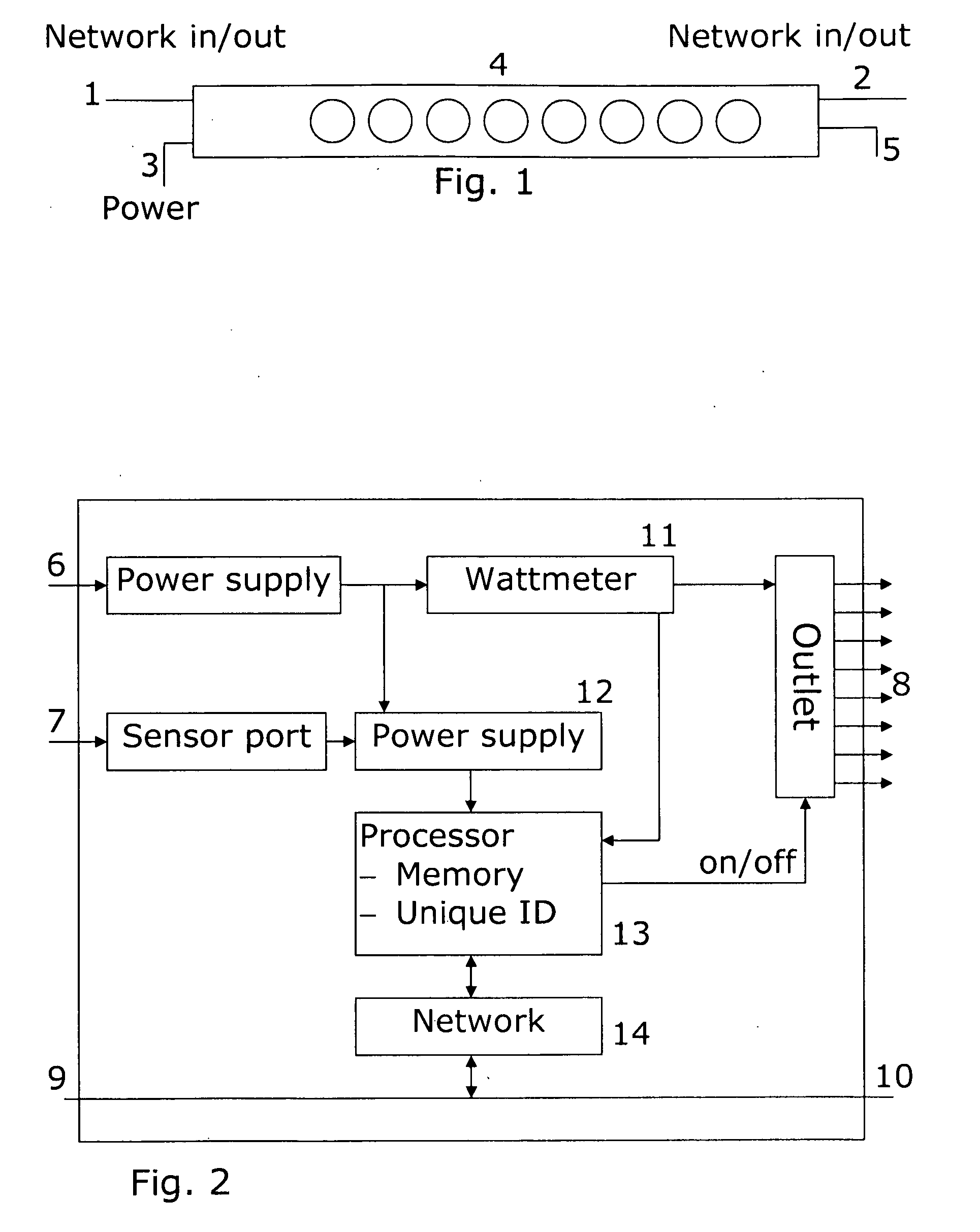
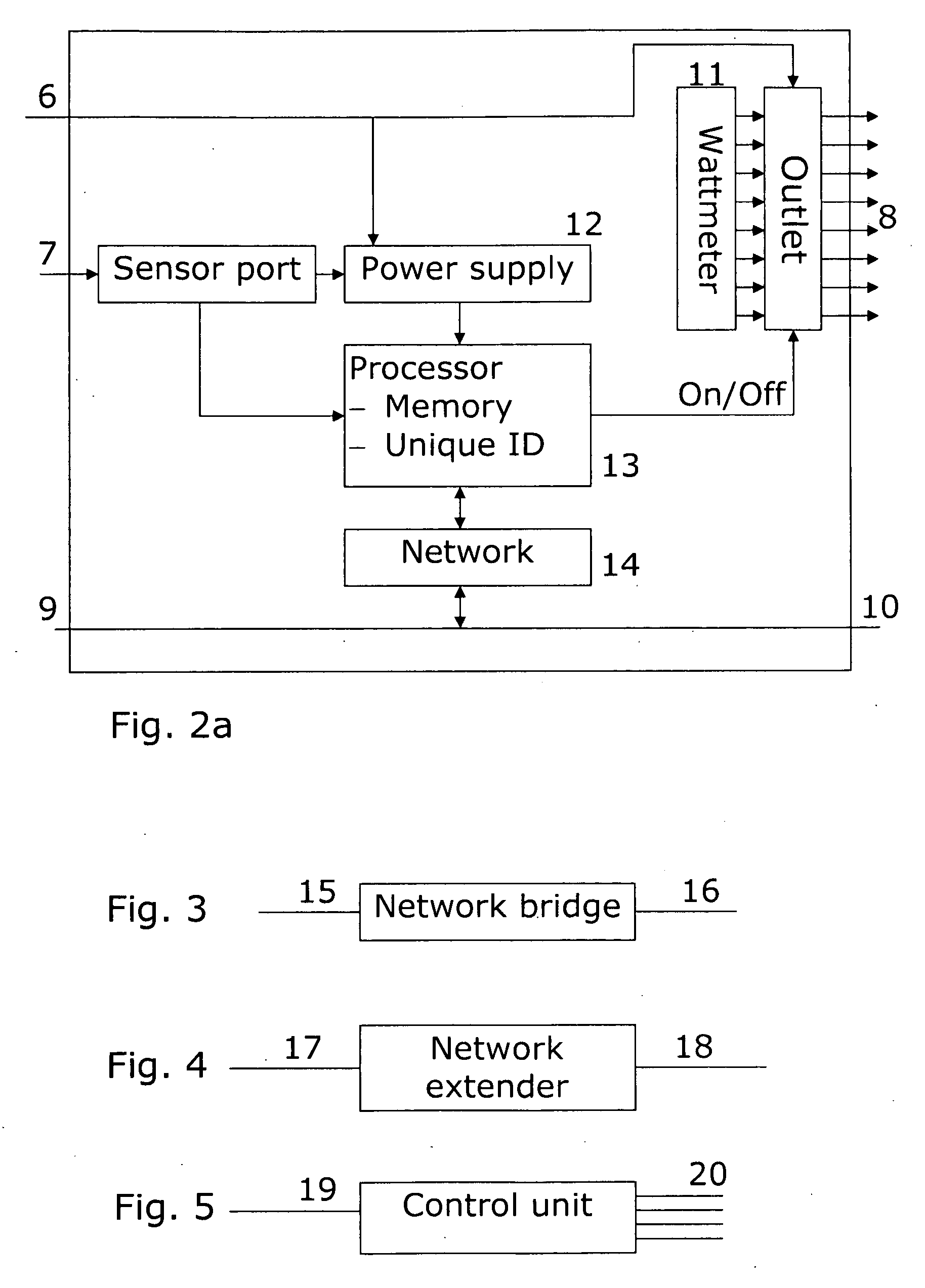
[0178]FIG. 1 illustrates an embodiment of a PDU comprising eight outlets. The PDU is able to switch the outlets on and off either by itself based on inputs from for example sensors connected to the PDU 4 via the sensor port 5 or the outlets may be controlled according to settings saved in the memory of the PDU. In a preferred embodiment of a PDU the network connection 2 may be omitted. However the network connection 2 may be used in an embodiment wherein it may be an advantage to “Daisy chain” units.

[0179] The PDU may be controlled by a user terminal, see FIG. 6, by establishing a communication to the user terminal through the network connection. In this...


PUM


Abstract

The present invention relates to a power switch, data system, interface and a data structure for controlling power outlets on one or more power switches. Each power switch comprises a sensor bus and watt meters in order to be able to monitor power consumption and environmental changes. Furthermore the power switches comprises a memory and a processor in order to be able to automatically control the power outlets without interference from a user terminal.

Description

FIELD OF THE INVENTION [0001] The present invention relates to apparatuses and methods for managing of electronic devices, for example computers, servers, printers, etc. More specifically, the present invention relates to Computer controlled power distribution units. BACKGROUND OF THE INVENTION [0002] In the past few years the number of servers, printers and other electronic devices has increased rapidly. The trend of an increasing number of electronic devices makes it very difficult for network administrators to control an entire network and its devices. For this reason, support tools have been developed in order to ease the burden experienced by administrators. One example of such support tool is power switches. [0003] Power switches that are able to control power to a number of devices exist. However, existing power switches have many drawbacks. Usually these power switches have a simple on and off functionality, although some may also perform a controlled on / off sequence. Howeve...

Claims


Application Information

Patent Timeline
IPC IPC(8): G05D11/00G06F1/18G06F1/26H04L12/12H04L12/26H04L12/28
CPCG06F1/266G06F2200/261H04L12/12H04L12/2602H04L12/2803Y04S40/168H04L12/2829H04L43/00H04L2012/285Y02B60/1296Y02B60/34H04L12/2825Y02D10/00Y02D30/50Y04S40/00
Inventor UZUNOVIC, NIKOLAJOHANSSON, MARTINDAMGAARD, ERIKRISAGER, MORTEN
Owner INT POWER SWITCH
Why Eureka
Try Eureka