Manifold assembly having a centralized pressure sensing package

a technology of pressure sensing package and manifold assembly, which is applied in the field of manifolds, can solve the problems of reducing the shifting performance of the transmission, requiring time-consuming and costly calibration of each valve, and posing numerous design challenges

Active Publication Date: 2007-12-06
EATON INTELLIGENT POWER LIMITED
View PDF6 Cites 9 Cited by
  • Summary
  • Abstract
  • Description
  • Claims
  • Application Information

AI Technical Summary

Benefits of technology

[0007]The invention is generally directed to a hydraulic manifold assembly containing a plurality of hydraulic channels that direct fluid to a centralized location and a package disposed at the centralized location to measure fluid pressure within the hydraulic channels. In one embodiment, the package includes one or more pressure transducers and a microprocessor, microcontroller, or state-m...

Problems solved by technology

Shifting is performed using open loop control of the valves, which requires time-consuming and costly calibration of each valve in the transmission system.
However, as the valves wear over time and as the viscosity of the transmission fluid changes due to age and contamination, the transmission system moves away from its initial calibration conditions, reducing the shifting performance of the transmission.
Piezoelectric pressure transducers are often a preferred choice in many sensing applications because of their low cost, but they pose numerous design challenges due to their non-linear response, low out...

Method used


Image

  • Manifold assembly having a centralized pressure sensing package
  • Manifold assembly having a centralized pressure sensing package
  • Manifold assembly having a centralized pressure sensing package

Examples


Embodiment Construction

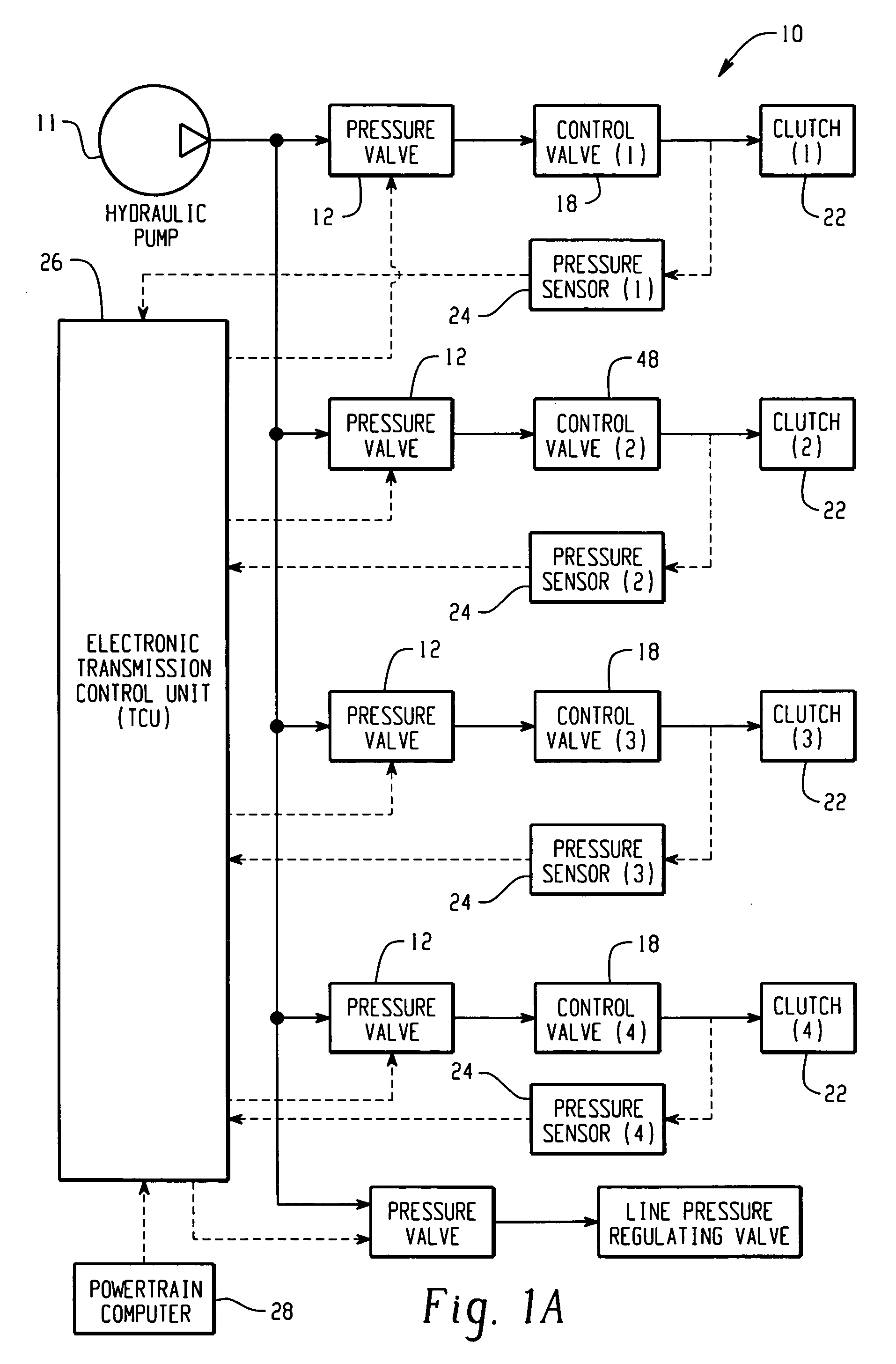
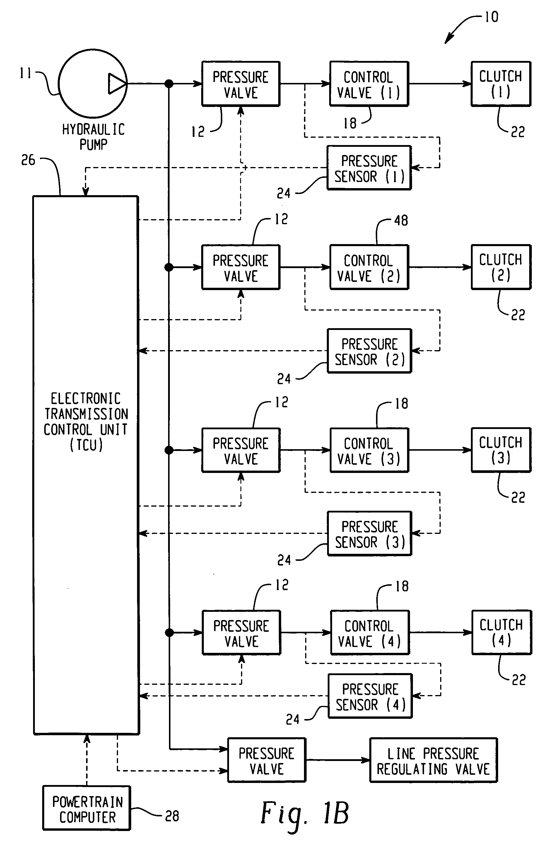
[0015]FIGS. 1A and 1B are representative block diagrams illustrating a closed-loop pressure control system 10 for a vehicle transmission in which a manifold assembly according to the invention can be used. Note that these figures are for illustrative purposes only to describe one possible application for the inventive package and are not meant to limit the scope of the invention in any way. Those of ordinary skill in the art will understand that the inventive system may be used in other applications without departing from the scope of the invention.

[0016]The system 10 may include a plurality of solenoid operated valves 12 supplied with pressurized hydraulic fluid from a pump 11, which may be driven by a transmission input shaft Each valve 12 supplies pressurized fluid along a conduit to a hydraulic control valve 18, and the output of each hydraulic control valve 18 is applied through a conduit to a hydraulically actuated clutch 22, as for example, a band clutch or plate clutch, for ...


PUM

PropertyMeasurementUnit
Pressureaaaaaaaaaa

Abstract

A hydraulic manifold assembly includes a manifold containing a plurality of hydraulic channels that direct fluid to a centralized location and a package disposed at the centralized location to measure fluid pressure at pressure ports corresponding to the hydraulic channels. The manifold assembly directs fluid to the single package rather than scattering fluid outputs to multiple sensor locations, simplifying the overall assembly configuration.

Description

TECHNICAL FIELD [0001]The present invention relates to manifolds for routing fluid, and more particularly to a manifold assembly having sensors for measuring fluid pressure in the manifold.BACKGROUND OF THE INVENTION [0002]Electronically controlled solenoid operated valves provide improved shifting capabilities for the transmission compared to hydro-mechanical shift control and, in particular, permits staged or progressive release and application of clutches, such as band clutches and / or plate clutches, for effecting smoother speed changes in the transmission. In currently-known production transmissions, these valve assemblies are mounted internally on the transmission valve body and supplied with pressurized fluid from a pump disposed in the transmission. Shifting is performed using open loop control of the valves, which requires time-consuming and costly calibration of each valve in the transmission system. However, as the valves wear over time and as the viscosity of the transmis...

Claims


Application Information

Patent Timeline
IPC IPC(8): F01L9/02
CPCF15B2211/513F15B2211/526F15B2211/6313F15B2211/6656F16H61/0009Y10T29/49398Y10T29/49945Y10T29/49002Y10T29/49Y10T29/49861F16H2059/683F16H61/00
Inventor DELL'EVA, MARK L.GREEN, TIMOTHY J.HERBERT, DAVID E.
Owner EATON INTELLIGENT POWER LIMITED
Why Eureka
Try Eureka