Analog circuit and method for multiplying clock frequency

a clock frequency and analog circuit technology, applied in the field of improved circuits and methods for generating clock signals, can solve problems such as difficulties in achieving internal clock generation circuits based on prior art relaxation oscillator circuits, and achieve the effect of increasing the accuracy of generated clock signals

Active Publication Date: 2007-12-06
TEXAS INSTR INC
View PDF1 Cites 14 Cited by
  • Summary
  • Abstract
  • Description
  • Claims
  • Application Information

AI Technical Summary

Benefits of technology

[0016]It is an object of the invention to provide a clock generator circuit based on a relaxation oscillator that provides increased accuracy of the generated clock signal.

Problems solved by technology

This has been difficult to achieve for internal clock generation circuits based on prior art relaxation oscillator circuits.

Method used


Image

  • Analog circuit and method for multiplying clock frequency
  • Analog circuit and method for multiplying clock frequency
  • Analog circuit and method for multiplying clock frequency

Examples


Embodiment Construction

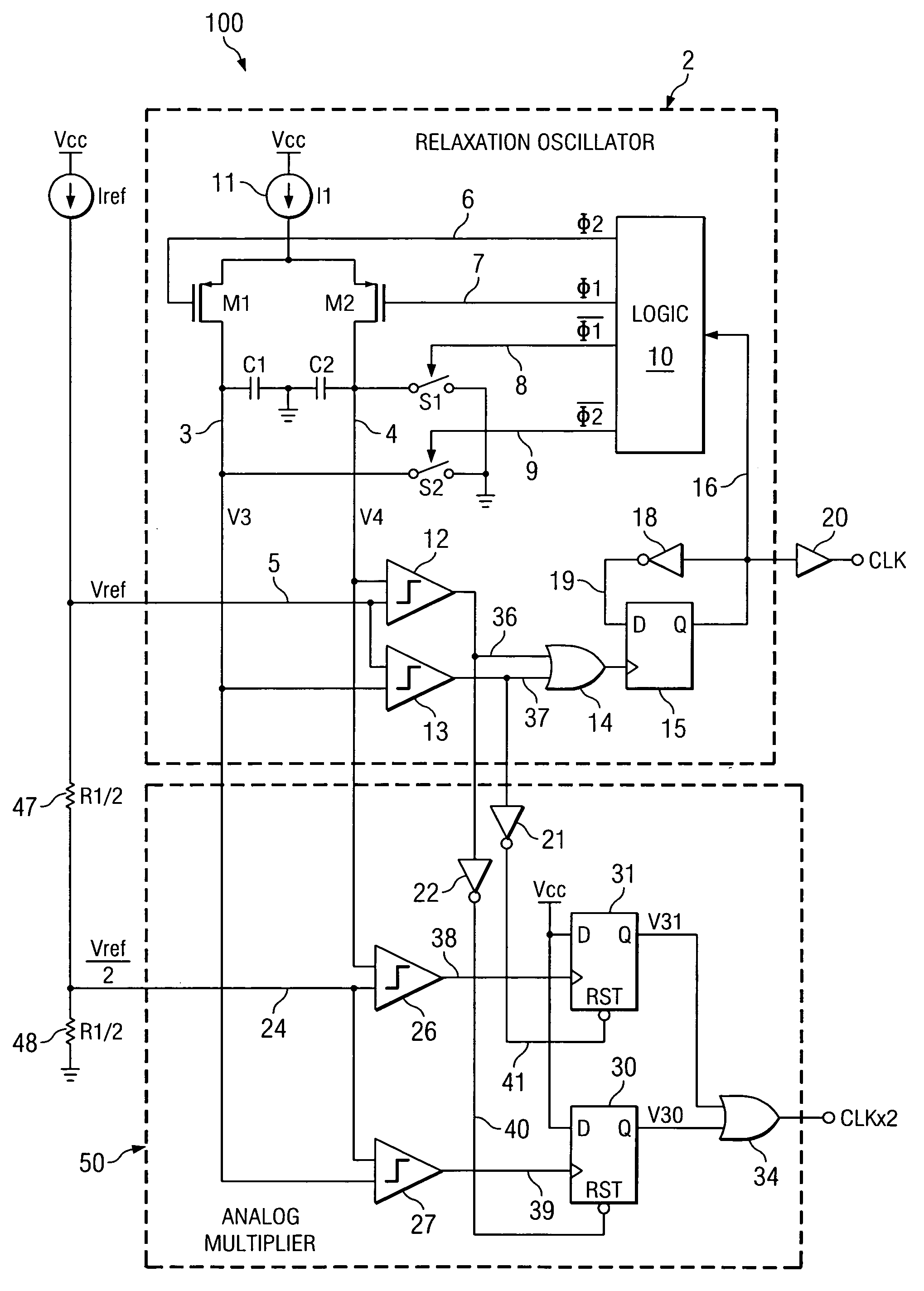
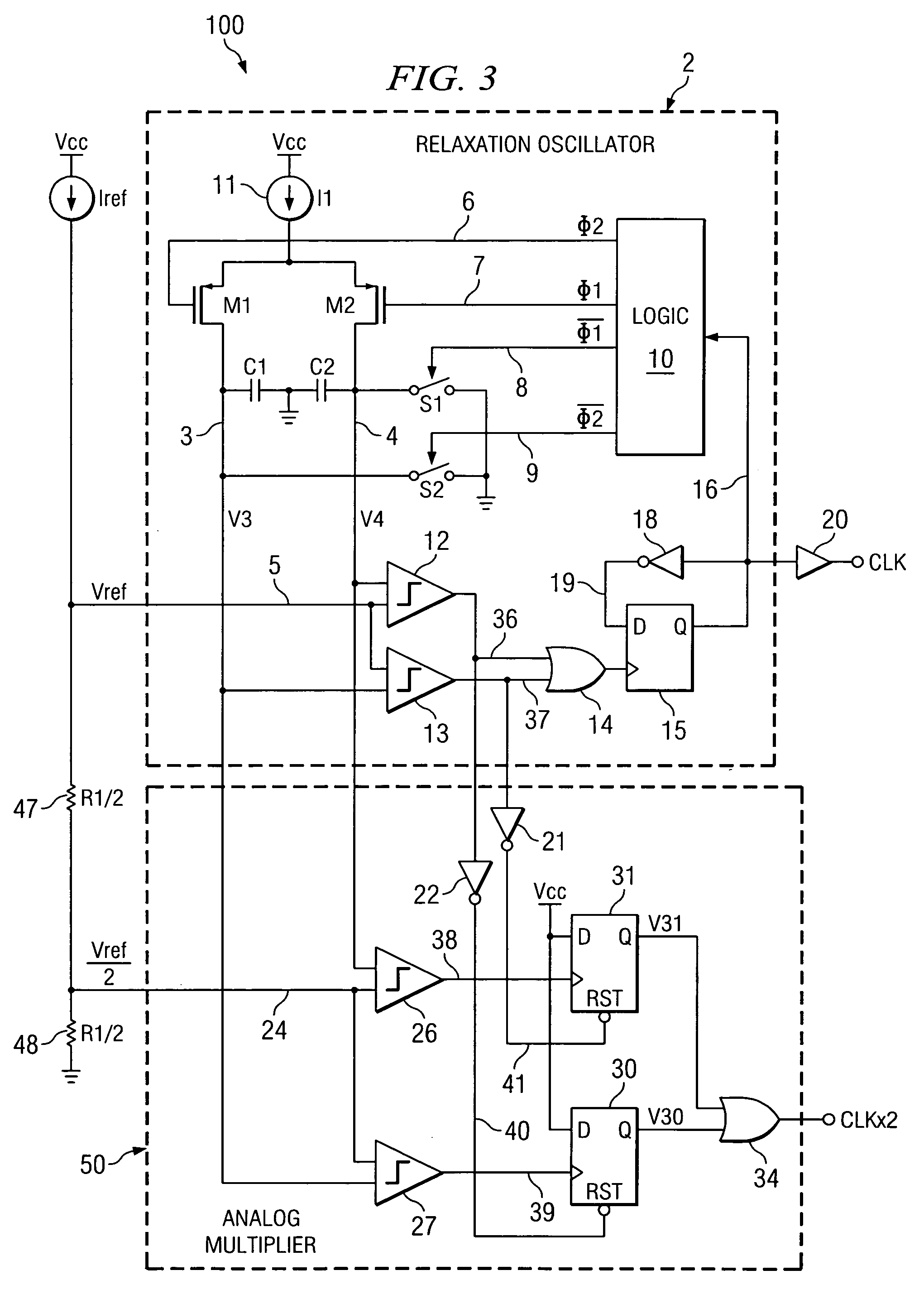
[0035]Referring to FIG. 3, clock generator circuit 100 includes a relaxation oscillator 2 which is the same as the one shown FIG. 1. Clock generator circuit 100 also includes an analog multiplier circuit 50 that generates a clock signal CLKx2 which has twice the relaxation oscillator frequency wherein the accuracy of the frequency of CLKx2 is substantially greater than would be the case if CLKx2 were generated by simply doubling the frequency of relaxation oscillator 2.

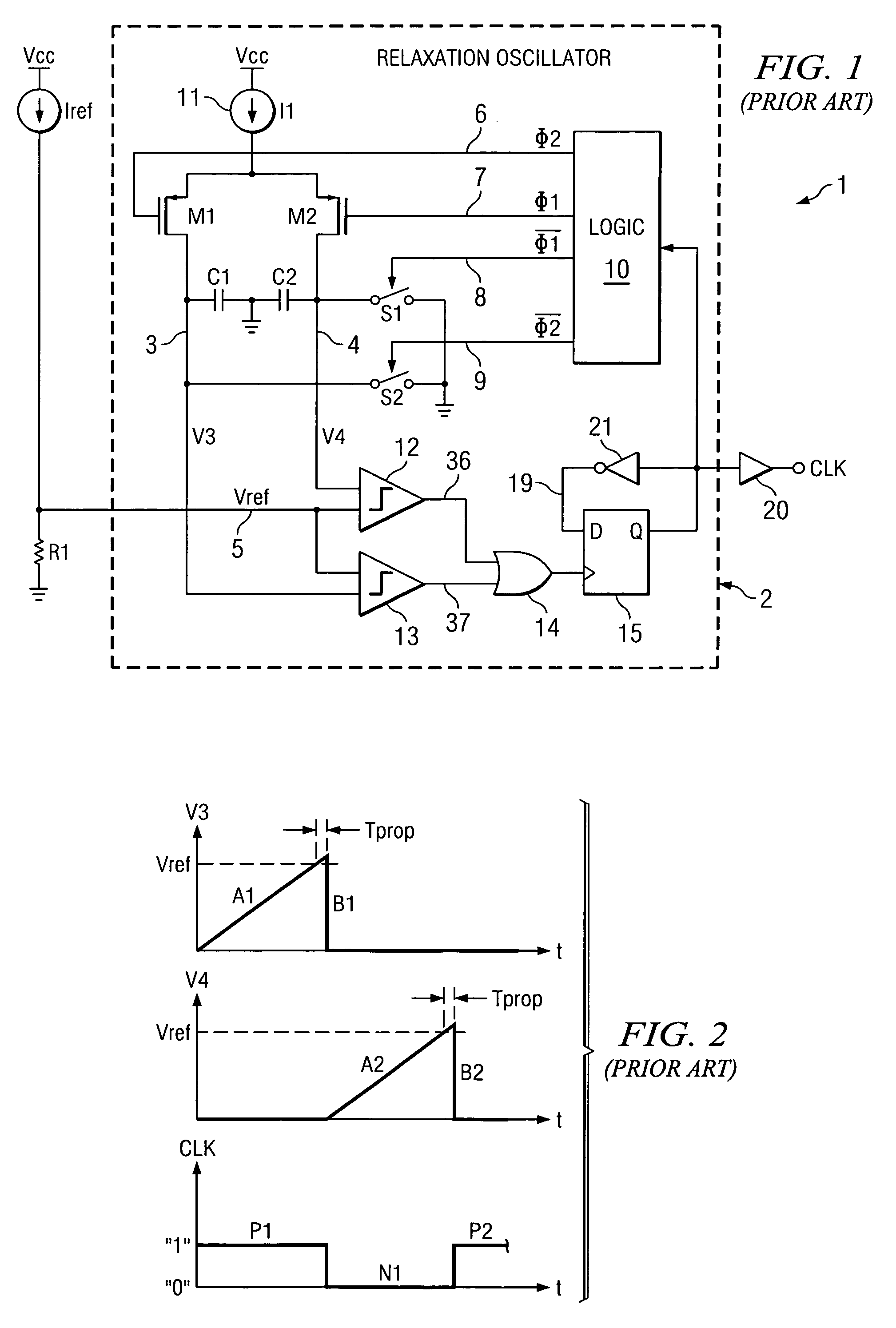
[0036]Relaxation oscillator 2 includes a current source 11 that supplies a current I1 to the sources of P-channel transistors M1 and M2, the gates of which are coupled by conductors 6 and 7, respectively, to outputs of logic circuit 10. Current source 11 can be implemented as shown in subsequently described FIG. 4. The drain of transistor M1 is connected by conductor 3 to one terminal of capacitor C1, one terminal of switch S2, and one input of comparator 13. Similarly, the drain of transistor M2 is connected by condu...


PUM


Abstract

A signal generating circuit includes a relaxation oscillator operating to alternately generate a first ramp signal that is periodic at a frequency of the relaxation oscillator and a second ramp signal that is periodic at the frequency of the relaxation oscillator and is out of phase with respect to the first ramp signal The first ramp signal is compared to a first reference voltage and the state of a first flip-flop is changed if the first ramp signal exceeds the first reference voltage. The second ramp signal is compared to the first reference voltage and the state of a second flip-flop is changed if the second ramp signal exceeds the first reference voltage. The first flip-flop is reset in response to a first level of the first ramp signal and the second flip-flop is reset in response to a second level of the second ramp signal. A logical ORing function is performed on an output of the first flip-flop and an output of the second flip-flop to produce an output signal having a frequency that is a multiple of the relaxation oscillator frequency.

Description

BACKGROUND OF THE INVENTION[0001]The present invention relates generally to improved circuits and methods for generating clock signals by multiplying a fundamental clock frequency, and more particularly to substantially increasing the accuracy of the multiplied clock frequency above the accuracy achievable in the prior art.[0002]“Prior Art”FIG. 1 shows a clock generation circuit 1 which includes a typical relaxation oscillator 2 that is believed to be representative of the closest prior art. Relatively “tight” frequency specifications are required for some integrated circuits including internal clock generators based on internal relaxation oscillators. For example, relatively tight frequency specifications are required for internal clock signals in integrated circuits which are designed to communicate over an RS232 interface. In the manufacture of such an integrated circuit, it may be desirable to perform a laser trimming operation on certain resistors in the integrated circuit at r...

Claims


Application Information

Patent Timeline
Patent Type & Authority Applications(United States)
IPC IPC(8): H03K3/26
CPCH03K3/0231H03K3/011
Inventor MOLINA, JOHNNIE
Owner TEXAS INSTR INC
Why Eureka
Try Eureka