Device and method to stabilize beam shape and symmetry for high energy pulsed laser applications

a laser and beam shape technology, applied in the field of pulsed gas discharge lasers, can solve the problems of corresponding degradation of beam uniformity, unstable pulse pulse intensity, and general non-symmetrical intensity along the long axis, so as to increase intensity symmetry increase intensity symmetry

Active Publication Date: 2007-12-06
CYMER INC
View PDF4 Cites 29 Cited by
  • Summary
  • Abstract
  • Description
  • Claims
  • Application Information

AI Technical Summary

Benefits of technology

[0013]An additional aspect of an embodiment may include a laser source comprising: an oscillator producing a beam, an amplifier amplifying the beam and a beam mixer increasing intensity symmetry along a selected axis of the beam. In one arrangement, the amplifier may output an amplified beam and the beam mixer may

Problems solved by technology

Fluctuations in laser beam shape and symmetry may lead to a corresponding degradation in beam uniformity at the exit of beam homogenizers.
This non-uniformity, in turn, can undesirably create regions of non-uniformly crystallized silicon.
While the pulse shape and intensity symmetry along the short

Method used


Image

  • Device and method to stabilize beam shape and symmetry for high energy pulsed laser applications
  • Device and method to stabilize beam shape and symmetry for high energy pulsed laser applications
  • Device and method to stabilize beam shape and symmetry for high energy pulsed laser applications

Examples


Embodiment Construction

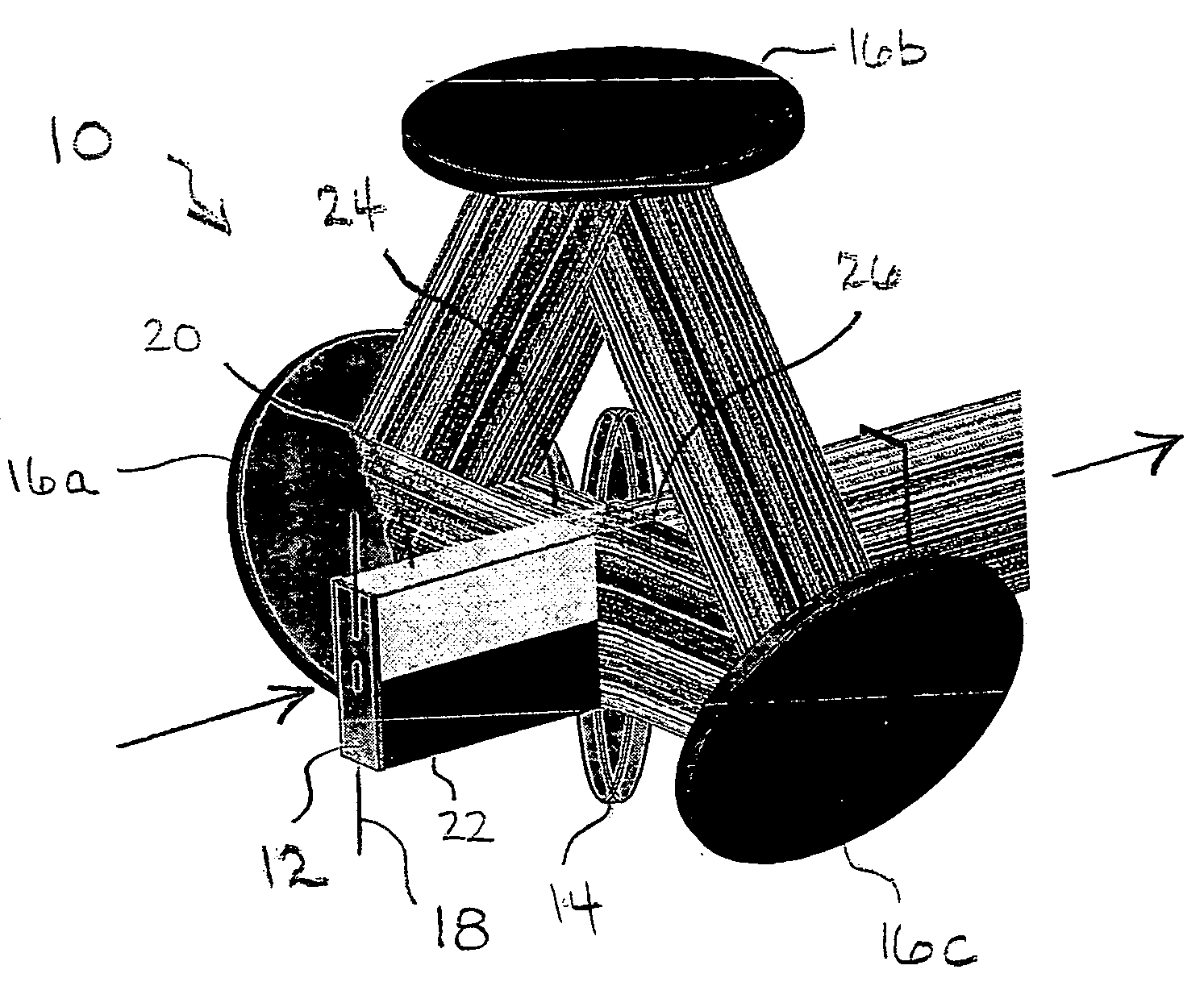
[0019]Referring initially to FIG. 1, a beam mixer 10 is shown for operation on a beam 12 (which for illustrative purposes has been shown as having an upper white-half and a lower black half). As explained in greater detail below, the beam mixer 10 can be used to alter the intensity profile of a beam, e.g. improving intensity symmetry along a selected axis of a beam, can be used to reduce beam coherency, or both. For the embodiment shown, the beam mixer 10 includes a beam splitter 14 and mirrors 16a-c.

[0020]For the arrangement shown in FIG. 1, the beam is initially incident upon the beam splitter 14 whereupon a portion of the beam is directed, via reflection, toward mirror 16a and the remainder is transmitted (with substantially no change in direction) through the beam splitter 14 and exits the beam mixer on an output beam path. In one setup, a beam splitter reflecting about forty to sixty percent of the incident light, e.g. fifty percent, may be used. For this setup, about fifty pe...


PUM


Abstract

A beam mixer for increasing intensity symmetry along a selected axis of a beam (wherein the beam extends from a first edge to a second edge along the axis) is disclosed and may include a plurality of mirrors establishing a spatially inverting path. For the beam mixer, the inverting path may have a beginning and an end and may be characterized in that a part of the beam near the first beam edge at the beginning of the path translates to the second beam edge at the end of the path. For this aspect, the beam mixer may further include an optic dividing the beam into first and second beam portions, the optic placing the first portion onto the inverting path and recombining the first and second portions onto a common path after the first portion has traveled along the inverting path thereby mixing the beam.

Description

CROSS-REFERENCE TO RELATED APPLICATIONS[0001]The present invention is related to copending, co-owned U.S. patent application entitled, “DEVICE AND METHOD TO CREATE A LOW DIVERGENCE, HIGH POWER LASER BEAM FOR MATERIAL PROCESSING APPLICATIONS” by Hofmann, attorney docket number 2006-0035-01 filed concurrently herewith, to copending, co-owned U.S. patent application entitled, “HIGH POWER EXCIMER LASER WITH PULSE STRETCHER” to Hofmann et al., attorney docket number 2006-0040-01 filed concurrently herewith, to U.S. application Ser. No. 11 / 261,948, titled “SYSTEMS AND METHODS FOR GENERATING A LASER SHAPED AS A LINE BEAM,” filed on Oct. 28, 2005, to U.S. application Ser. No. 10 / 781,251, titled “VERY HIGH ENERGY, HIGH STABILITY GAS DISCHARGE LASER SURFACE TREATMENT SYSTEM,” filed on Feb. 18, 2004, to U.S. application Ser. No. 10 / 884,101, titled “LASER THIN FILM POLY-SILICON ANNEALING OPTICAL SYSTEM,” filed on Jul. 1, 2004, and to U.S. application Ser. No. 11 / 138,001, titled “SYSTEMS AND MET...

Claims


Application Information

Patent Timeline
IPC IPC(8): G02B27/00G02B1/10
CPCG02B27/0977H01S3/005H01S3/225G02B19/0061G02B19/0052G02B19/0028G02B19/0095H01S3/05H01S3/08
Inventor HOFMANN, THOMAS
Owner CYMER INC
Why Eureka
Try Eureka