
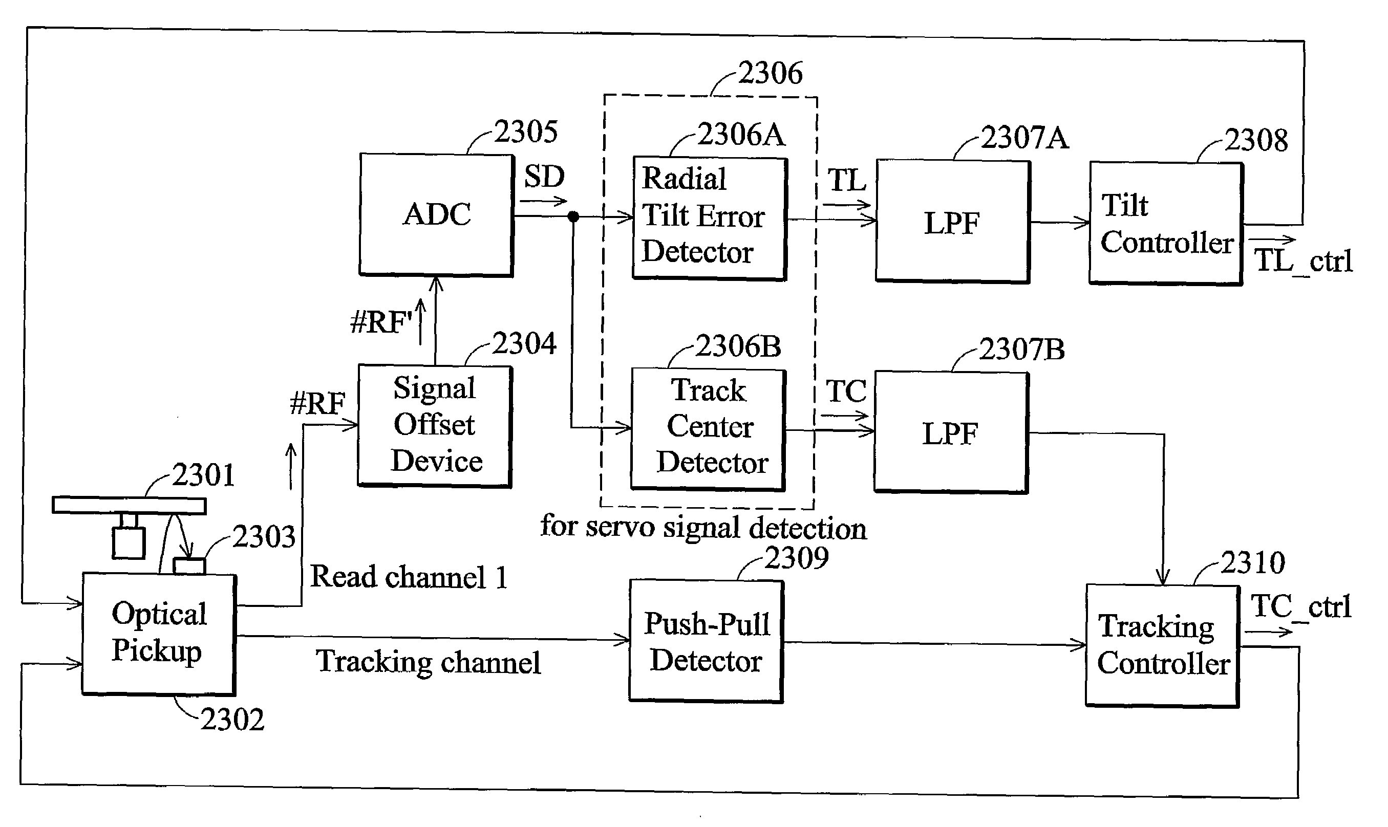
Apparatus and methods for light spot servo signal detection

a technology of servo signal and apparatus, which is applied in the field of apparatus and methods for tracking center error and tilt error detection of optical discs, can solve the problems of inefficient control loop time, long period of time required before the rf signal #rf, and inability to achieve the effect of rf signal #rf,

Inactive Publication Date: 2007-12-06
MEDIATEK INC
View PDF11 Cites 19 Cited by
  • Summary
  • Abstract
  • Description
  • Claims
  • Application Information

AI Technical Summary

Problems solved by technology

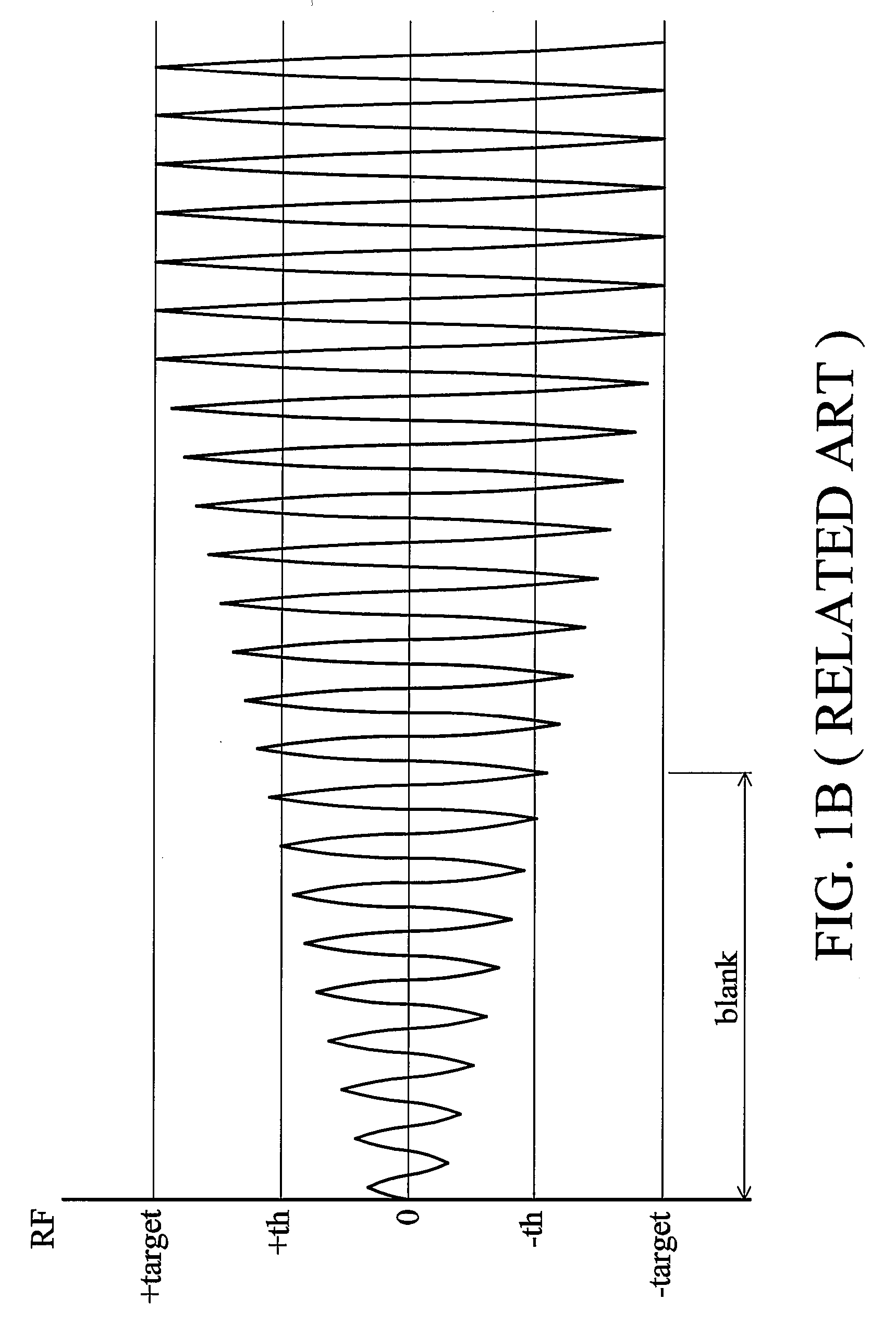
Time required for the control loops to approximate the RF signal #RF to the target level, however, may be inefficient.
If the convergence ratio of the control loops is set too low, a long period of time is required before the RF signal #RF reaches the target level.
Otherwise, if the convergence ratio is set too high, the control loops may be unstable, reducing signal quality for the analog to digital converter 204.
Thus, determination for step sizes of the gain control loop and offset control loop is an important issue.
In the prior art, the asymmetry of the waveform of the recorded data reproduction signal is measured in analog domain, costing much layout space and raising the design complexity.
Signal quality can deteriorate significantly with servo error such as tilt and mis-track of a disc as recording density becomes higher not only in a disc only for reproduction such as a DVD-ROM but also in a recordable disc such as a DVD-RAM.
In particular, in the recordable disc, the recording quality deteriorates due to the influence of the servo error when the servo error occurs during recording and the deterioration of the quality of the signal becomes severe due to the servo error during the reproduction of an applicable part.
However, sample hold circuits 903A and 903B are analog circuitries, which have poorer accuracy opposite to digital circuitry.
Thus, it is difficult to detect Read channel 1 signal #RF more frequently in a short period of time using the analog sample hold circuits 903A and 903B, deteriorating the detection accuracy.
To detect Read channel 1 signal #RF more frequently in a short period of time, more complexity sample hold circuits are required, however, increasing the cost and size of the circuit detecting track center error and tilt error of a DVD-RAM disc.

Method used


Image

  • Apparatus and methods for light spot servo signal detection
  • Apparatus and methods for light spot servo signal detection
  • Apparatus and methods for light spot servo signal detection

Examples


first embodiment

[0070]Please refer to FIG. 19. FIG. 19 is a diagram illustrating an asymmetry measurement apparatus 1900 according to the invention. The asymmetry measurement apparatus 1900 comprises a signal adjusting module 1910, an Analog to Digital Converter (ADC) 1904, a detection unit 1905, an asymmetry calculation unit1906, and a comparator 1907. The signal adjusting module 1910 adjusts the recorded data reproduction signal S1. The ADC 1904 is coupled to the signal adjusting module 1910 for converting the adjusted recorded data reproduction signal S1 into a digital signal S2. The detection unit 1905 is coupled to the ADC 1904 for detecting plurality values of the digital signal S2 according to a control signal C2. That is, the detection unit 1905 detects the plurality values of the digital signal S2 when the control signal C2 is high, and the detection unit 1905 does not detect the plurality values of the digital signal S2 when the control signal C2 is low. The plurality values of the digita...

second embodiment

[0075]Please refer to FIG. 20. FIG. 20 is a diagram illustrating an asymmetry measurement apparatus 2000 according to the invention. The asymmetry measurement apparatus 2000 is similar with the asymmetry measurement apparatus 1900 in FIG. 19 except the signal adjusting module 1910 is replaced with the signal adjusting module 2010. The component denotes with the same numerical numbers operates in similar way and have similar functions. Thus, for the sake of brevity, the description of the components of FIG. 20 similar to those in FIG. 19 is omitted.

[0076]The signal adjusting module 2010 comprises a High-Pass Filter (HPF) 2001, a VGA 2002, and an equalizer 2003. The HPF 2001 is disposed for filtering the recorded data reproduction signal S1. The VGA 2002 is coupled to the HPF 2001 for amplifying the filtered recorded data reproduction signal S1. The equalizer 2003 is coupled to the VGA 2002 for equalizing the amplified recorded data reproduction signal S1. The operating bandwidth of t...


PUM

PropertyMeasurementUnit
areaaaaaaaaaaa
thresholdaaaaaaaaaa
transmissionaaaaaaaaaa

Abstract

An apparatus for light spot servo signal detection for reading an optical recording medium having a plurality of non-writable areas between writable data areas containing address information. An optical pickup provides a light spot to the non-writable areas of the optical recording medium with a predetermined state according to a control signal, and detects optical reflecting signals from the optical recording medium to generate a detection signal. A signal adjusting module offsets signal levels of the detection signal to an operating range to generate an offset shifted detection signal. An analog to digital converter digitizes the offset shifted detection signal to generate a digital signal. A detection circuit detects the servo detection signal according to the digital signal.

Description

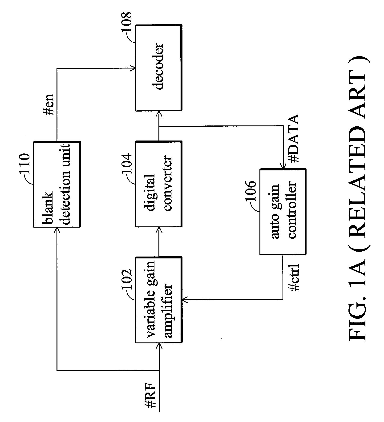
CROSS REFERENCE TO RELATED APPLICATIONS[0001]This application claims the benefit of U.S. Provisional Applications No. 60 / 803,881, 60 / 803,882, 60 / 803,884 and 60 / 811,022, which are all filed 2006 / 06 / 05.BACKGROUND OF THE INVENTION[0002]1. Field of the Invention[0003]The invention relates to apparatus and methods for light spot servo signal detection, and more particularly to apparatus and methods for track center error and tilt error detection of optical discs.[0004]2. Description of the Related Art[0005]FIG. 1A shows a conventional optical storage device. Conventionally, data stored in an optical disc is amplified and digitized to a target level before decoding. The variable gain amplifier 102, analog to digital converter 104 and auto gain controller 106 form an AGC loop to adjust the gain of the RF signal #RF. An extra data path is formed by a blank detection unit 110 to detect blankness of the RF signal #RF, where the blankness is corresponding to at least a blank sector of a track ...

Claims


Application Information

Patent Timeline
Patent Type & Authority Applications(United States)
IPC IPC(8): G11B7/00
CPCG11B7/094G11B7/0941G11B2020/1287G11B20/10009G11B7/0956
Inventor CHENG, YUHCHEN, CHIH-CHINGLIAO, CHIA-WEIYU, MING-JIOULAN, KUO-JUNGCHOU, SHU-HUNGLIN, YU-HSUAN
Owner MEDIATEK INC
Learn More