Data Transfer Method and System for Use in Atm Communication

a data transfer and atm communication technology, applied in the field of atm communication data transfer methods and systems, can solve the problems of inability to determine the transmission sequence of atm cells stored in different slave parts on the transmission side, and cells stored in the master part in a different sequence, so as to achieve the effect of reliably receiving atm cells

Inactive Publication Date: 2007-12-06
NEC CORP
View PDF4 Cites 0 Cited by
  • Summary
  • Abstract
  • Description
  • Claims
  • Application Information

AI Technical Summary

Benefits of technology

[0021] When releasing the mask of the physical layer processing part only, it is easy to mask all of the other physical layer processing parts than the physical layer processing part holding the ATM cell to be transferred. This is preferable since novel functions can be added without requiring significant change in the configuration shown in FIG. 1. However, it is also possible to employ a method of masking the output of a physical layer processing part when the physical layer processing part holds an ATM cell, and releasing the mask when the physical layer processing part is designated as a destination of transfer.
[0022] According to the data transfer method and system for use in ATM communication according to the present invention, the reception side receives the transmission sequence from the transmission side, and the ATM layer processing part reads the ATM cells received by the physical layer processing parts in accordance with the transmission sequence. Therefore, the configuration of the present invention has an advantage that the ATM layer processing part is able to reliably receive the ATM cells in the same sequence as they are transmitted on the transmission side.
[0023] Additionally, the addresses of the physical layer processing parts are used as transmission order signals, and in the reception side, the ATM cell outputs of the physical layer processing parts other than the physical layer processing parts corresponding to the addresses are masked. This configuration makes it possible to add novel functions without requiring significant change in the configuration shown in FIG. 1.

Problems solved by technology

This may entail a problem that the sequence of the ATM cells at the time when they are received by the reception side is possibly changed from the sequence when they are output from the transmission side, depending on the reception condition of the UTOPIA slave parts.
In this case, it is impossible to determine the transmission sequence of the ATM cells stored in the different slave parts on the transmission side.
This means that the system, in which the slave parts are sequentially polled, has a disadvantage that the cells are stored in the master part in a different sequence from that on the transmission side.

Method used


Image

  • Data Transfer Method and System for Use in Atm Communication
  • Data Transfer Method and System for Use in Atm Communication
  • Data Transfer Method and System for Use in Atm Communication

Examples


first embodiment

[0042] A first embodiment of the present invention will be described with reference to FIG. 3.

[0043]FIG. 3 is an explanatory diagram illustrating block configuration of a data transfer system for ATM communication according to an embodiment of the present invention. In FIG. 3, a transmission side shelf 1 is connected to a reception side shelf 2 with a plurality of transmission bands.

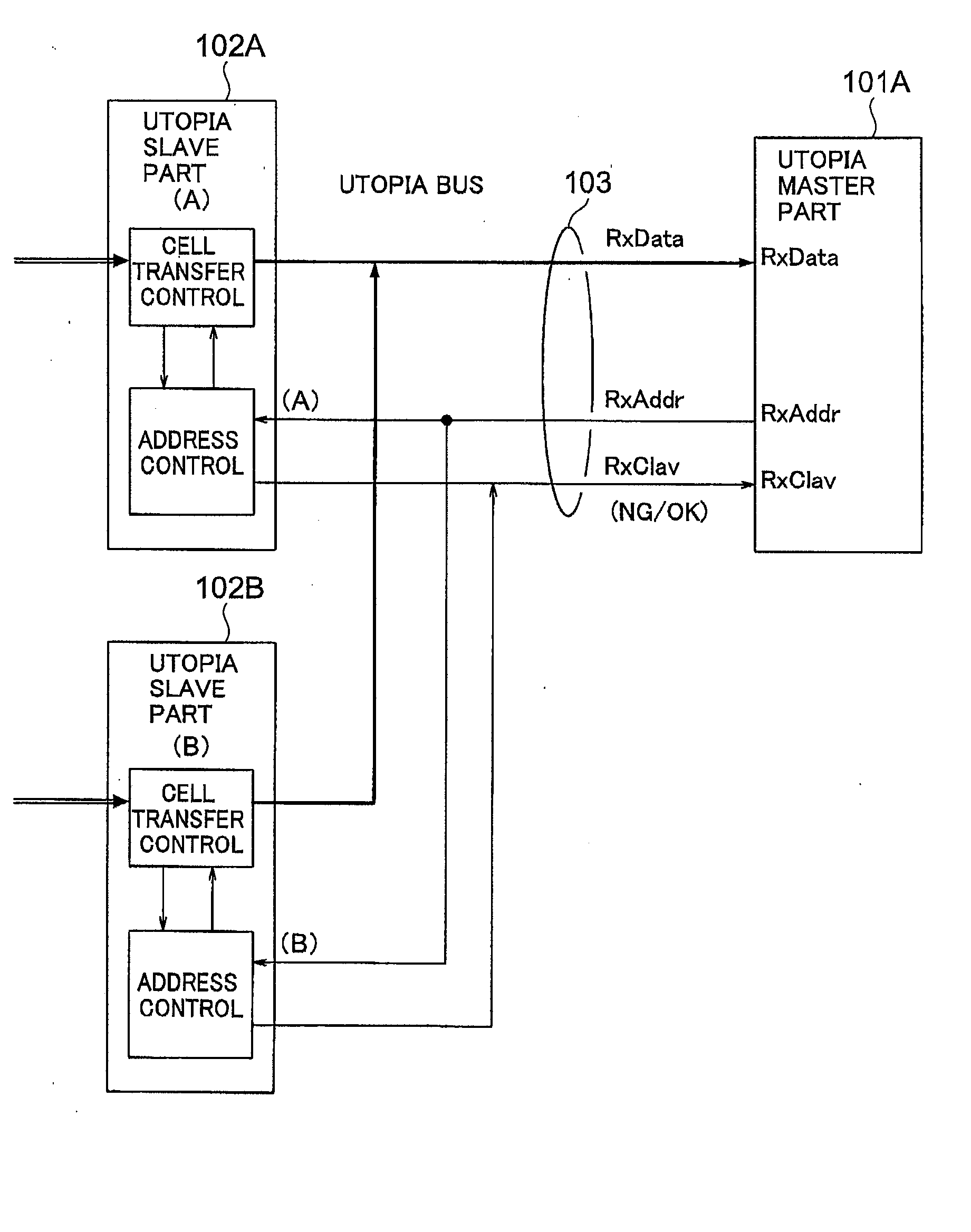
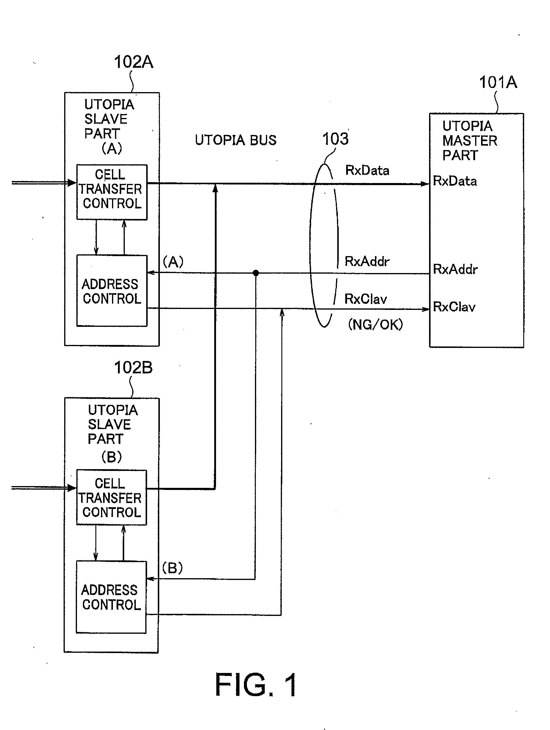
[0044] The transmission side shelf 1 has one UTOPIA master part (hereafter, referred in short as the master part) 11 formed by an ATM layer processing part, a plurality of UTOPIA slave parts (hereafter, referred in short as the slave parts) 12A, 12B, . . . formed by physical layer processing parts, a UTOPIA bus 13, and an address monitor part 14. The master part 11 and the slave parts 12A, 12B, . . . are connected by the UTOPIA bus 13. The address monitor part 14 is connected to the UTOPIA bus 13 to monitor ATM cells sequentially transferred onto the UTOPIA bus 13 and sequentially read destination addr...


PUM


Abstract

The transmission sequence is matched between the reception side and the transmission side when communication is performed by forming a plurality of transmission bands between shelves each formed of physical layer processing parts (transmission processing parts) and an ATM layer processing part (cell processing part) with the use of a UTOPIA interface. For this purpose, the address monitor part (14) of the transmission side shelf (1) sequentially reads destination addresses of ATM cells transmitted from the master part (11) of the cell processing part and sends the read addresses as cell order signals in the same sequence as they are received, to the cell output switching part (24) of the reception side shelf (2). The cell output switching part (24) releases the mask such that an ATM cell is output by only one of the slave parts (22A, 22B, . . . ) of the transmission processing parts corresponding to the address received as the cell order signal, while blocking by masking the ATM cell outputs of the slave parts having the other addresses regardless of whether they store ATM cells or not. The destination addresses are assigned to each pair of the slave parts (12A, 22A, 12B, 22B, . . . ).

Description

TECHNICAL FIELD [0001] The present invention relates to a data transfer method and system for use in ATM (Asynchronous Transfer Mode) communication, and particularly to a data transfer method and system for use in ATM communication for transferring data between shelves with the use of ATM cells. BACKGROUND ART [0002] ATM apparatuses for multiplexing / demultiplexing ATM cells include an interface standardized between devices and named UTOPIA (Universal Test and Operation PHY (Physical Layer Protocol) Interface for ATM). This interface is proposed by The ATM Forum. [0003] The UTOPIA interfaces are classified into several levels. UTOPIA level 2 among these levels defines an interface principally between a single ATM layer processing part and a plurality of physical (PHY) layer processing parts. [0004] The interfaces up to the ATM layers are standardized, whereas various types of transmission medium are used in the physical layer processing parts. Therefore, the UTOPIA interfaces having ...

Claims


Application Information

Patent Timeline
Patent Type & Authority Applications(United States)
IPC IPC(8): H04L12/56H04L12/70
CPCH04L12/5601H04L2012/5665H04L2012/5614H04L2012/5603
Inventor YOSHIDA, MITSUTAKA
Owner NEC CORP
Why Eureka
Try Eureka