Insulated support tool

a technology of support tool and insulating film, which is applied in the direction of coating, mechanical equipment, spray nozzles, etc., can solve the problems of easy peeling of the coating film on the object to be coated, complicated operation of masking, etc., and achieve the effect of convenient masking

Inactive Publication Date: 2016-03-24
AKEBONO BRAKE IND CO LTD
View PDF33 Cites 5 Cited by
  • Summary
  • Abstract
  • Description
  • Claims
  • Application Information

AI Technical Summary

Benefits of technology

[0030]Further, the caliper may be formed so that a film thickness is gradually thinner toward a region not needing powder from a powder adhering region. Thereby, occurrence of coating removal or the like that is feared in the conventional masking by a plug and a tape can be restrained.
[0031]According to the present invention, masking can be performed more easily than in the prior art.

Problems solved by technology

Therefore, an operation of masking is complicated, and it is feared that a coating film on the object to be coated and coating films which adhere to the tape and the cap for masking are integrated, and when the tape and the cap for masking are detached, the coating film on the object to be coated easily peels off.

Method used


Image

  • Insulated support tool
  • Insulated support tool
  • Insulated support tool

Examples


embodiment

Caliper

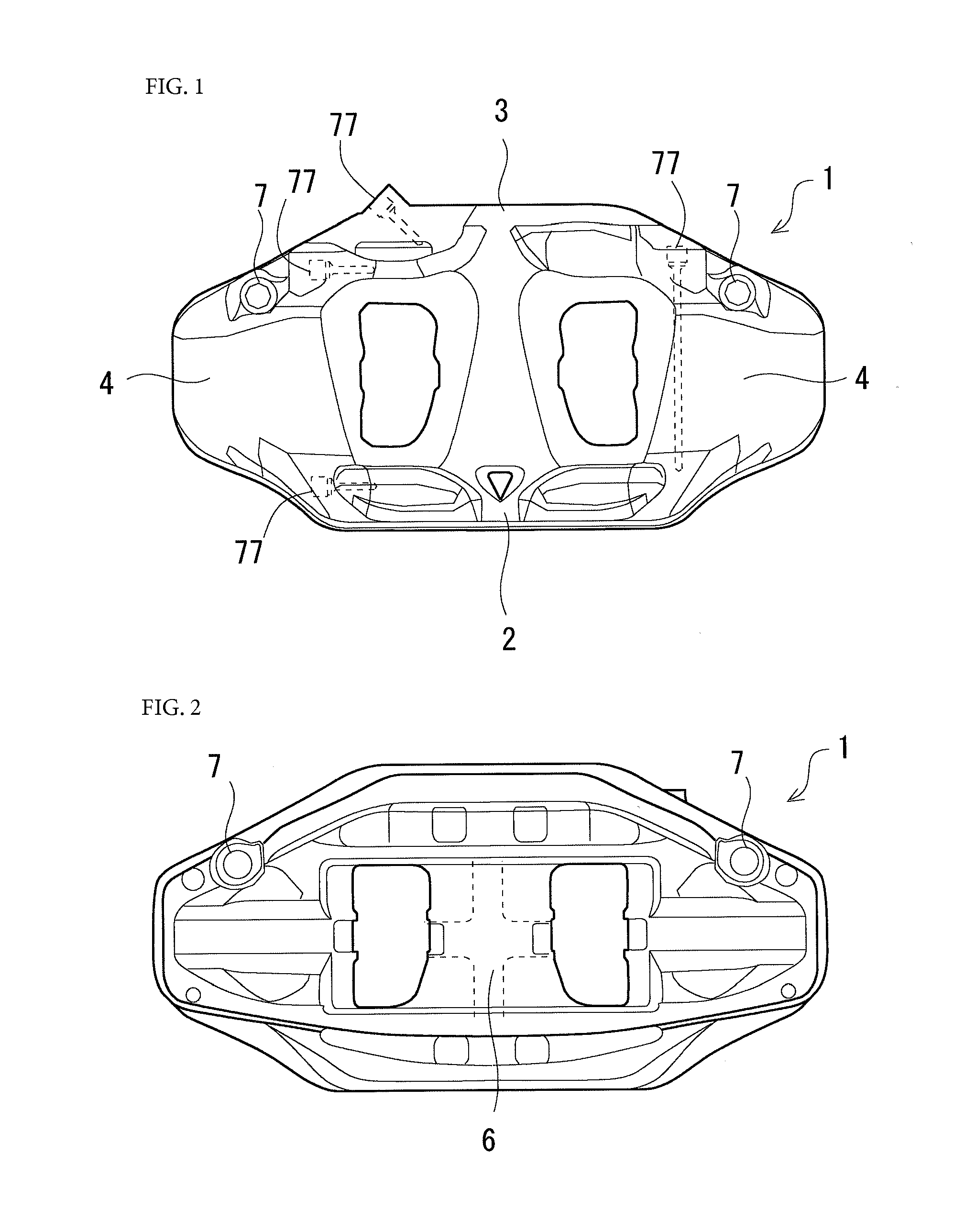
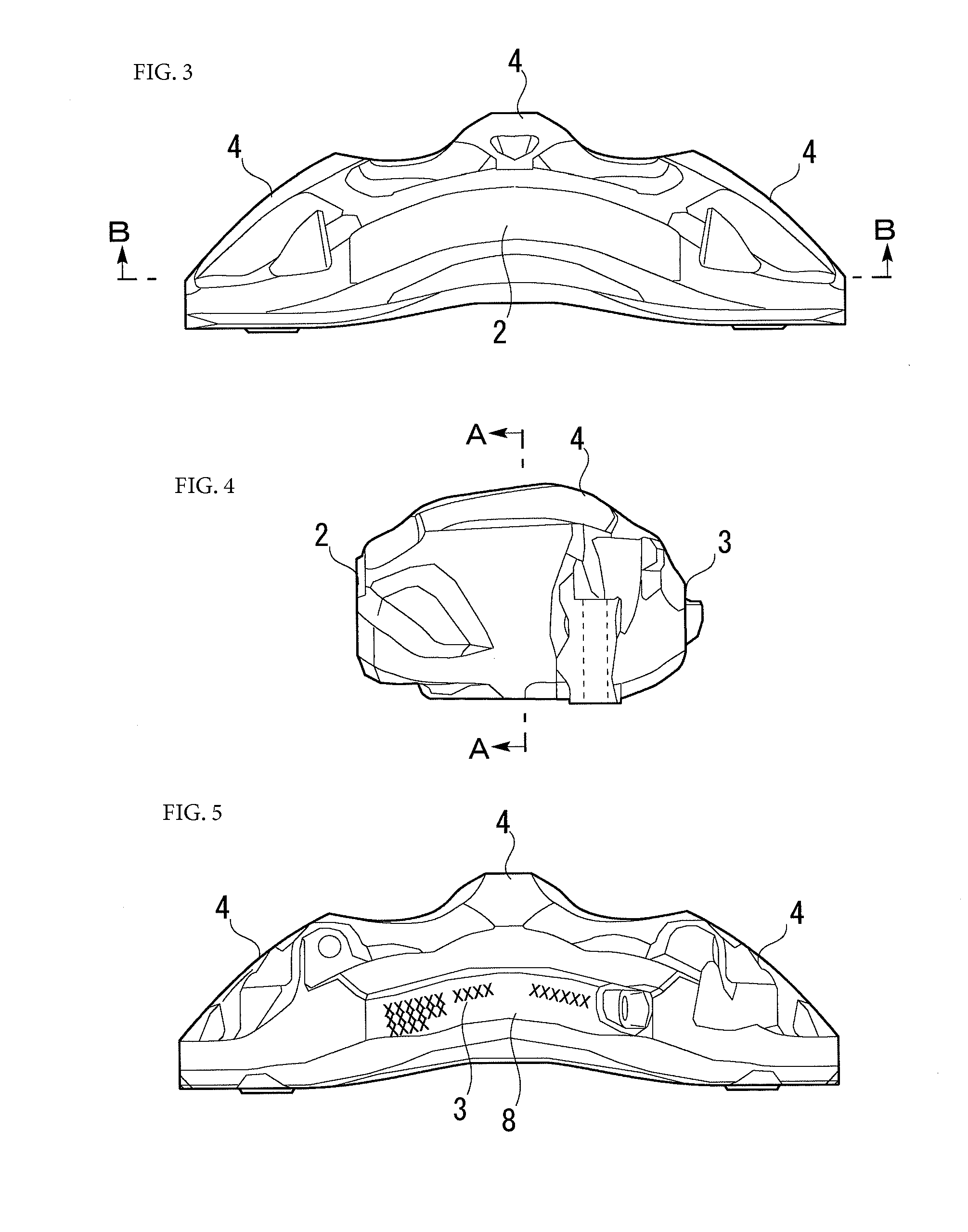
[0051]To begin with, a caliper body 1 (hereinafter, also simply called a caliper 1) of a disk brake of an automobile that is electrostatically coated will be described. FIG. 1 to FIG. 6 illustrate a caliper according to the embodiment. The caliper 1 (corresponding to a workpiece of the present invention) is to be used in an opposed piston type disk brake, and is an aluminum caliper integrally formed from an aluminum alloy. The caliper 1 includes a recessed portion 6 that accommodates a disk rotor which rotates with a wheel (Not illustrated. Hereinafter, also simply called a rotor), and a brake pad (not illustrated), and is widely opened. The caliper 1 is made by integrally forming a first body portion 2 and a second body portion 3 that are disposed at both sides (an outer side and an inner side) in an axial direction of the rotor, and a connecting portion 4 that connects both the body portions 2 and 3. In a first embodiment, six cylinders 5 in total are provided in the entire...


PUM

PropertyMeasurementUnit
adhesionaaaaaaaaaa
thicknessaaaaaaaaaa
torqueaaaaaaaaaa

Abstract

To provide an art that can perform masking more easily than in the prior art. A support tool that is used in a powder coating system that electrostatically attaches powder to a workpiece, and supports the workpiece, wherein in the support tool, a region that is in contact with a part of a region not needing powder in the workpiece is formed of an insulator, and restrains adhesion of the powder to the part of the region not needing powder in the workpiece.

Description

TECHNICAL FIELD[0001]The present invention relates to a support tool, a powder coating system, a powder coating method and a caliper.BACKGROUND ART[0002]Coating is applied to industrial products for the purpose of rust prevention, decoration and the like. Regions not needing coating are present in industrial products, and masking is applied to the regions not needing coating so that coating materials do not adhere to the regions not needing coating. As the conventional masking method, there is the art which attaches a tape and a cap for masking to a region not needing coating, and detaches the tape and the cap for masking after coating. Further, for example, Patent Document 1 discloses an art of sucking a powder coating material on inner circumferential surfaces of a hub hole and a bolt hole of a wheel of a center cap type. Further, Patent Document 2 discloses a masking device that performs masking for a component to be coated by ejection of pressure air at the time of coating by a ...

Claims


Application Information

Patent Timeline
Patent Type & Authority Applications(United States)
IPC IPC(8): B05B15/04B05B5/08B05D1/12F16D65/00
CPCB05B15/0431F16D65/0068B05D1/12B05B5/082B05B5/081B05B13/0221B05D1/32B05D3/0254F16D2250/0046F16D2055/0016B05D1/06B05B12/18B05B14/10B05B12/20B05B12/16B05B1/14B05B13/06
Inventor OSAWA, TOMOMASAIWATA, YUKIOMASUDA, JUNGONIWANO, YUYA
Owner AKEBONO BRAKE IND CO LTD
Why Eureka
Try Eureka