
Timer with network synchronized time base

a time base and timer technology, applied in the field of electric programmable event timers, can solve the problems of high cost of software design software to run a microprocessor-based timer, large latency of microprocessors and software instructions, and large system resources consumed by microprocessors and software. the effect of high accuracy

Active Publication Date: 2007-12-06
MACOM CONNECTIVITY SOLUTIONS LLC
View PDF6 Cites 20 Cited by
  • Summary
  • Abstract
  • Description
  • Claims
  • Application Information

AI Technical Summary

Benefits of technology

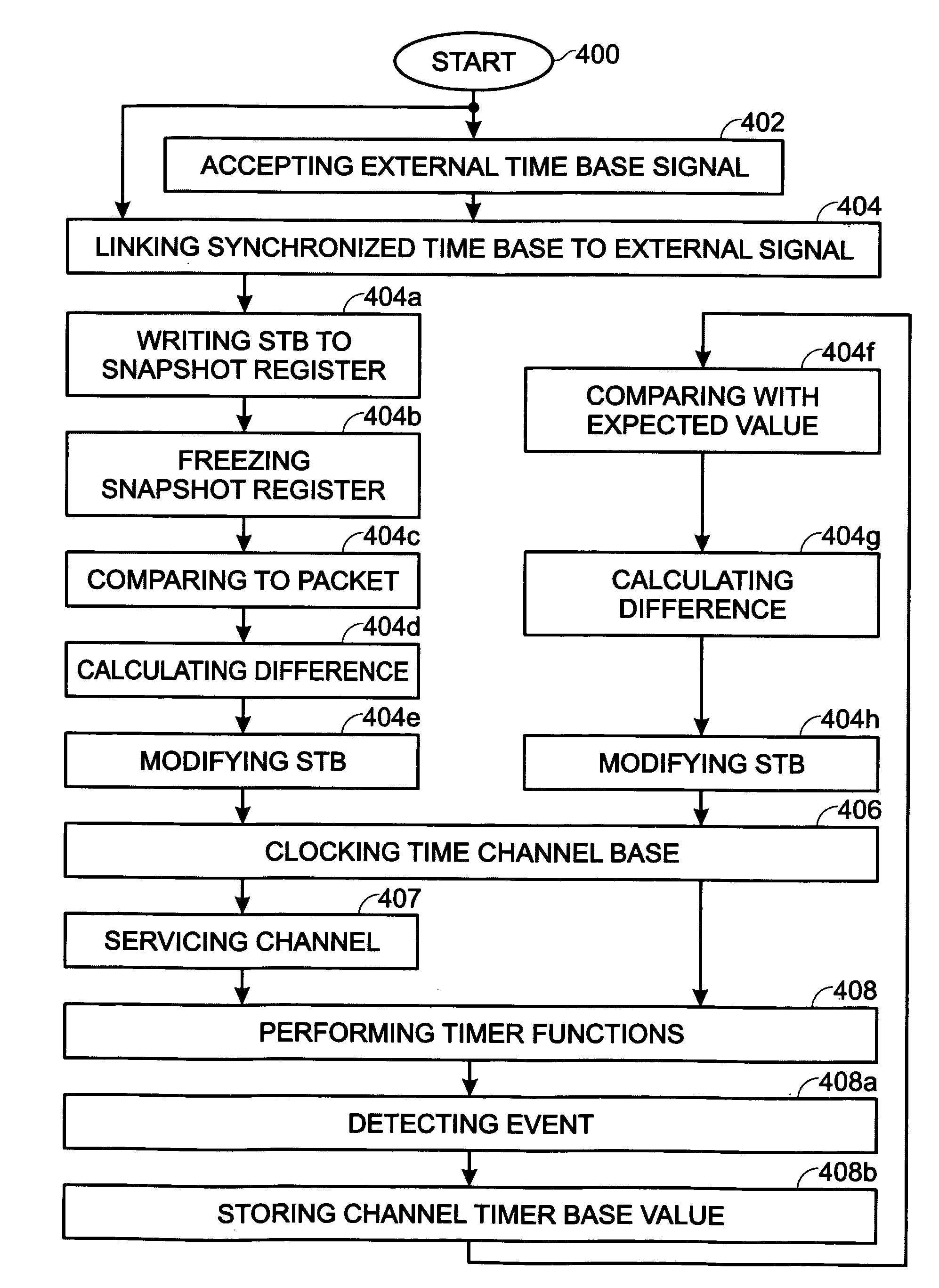
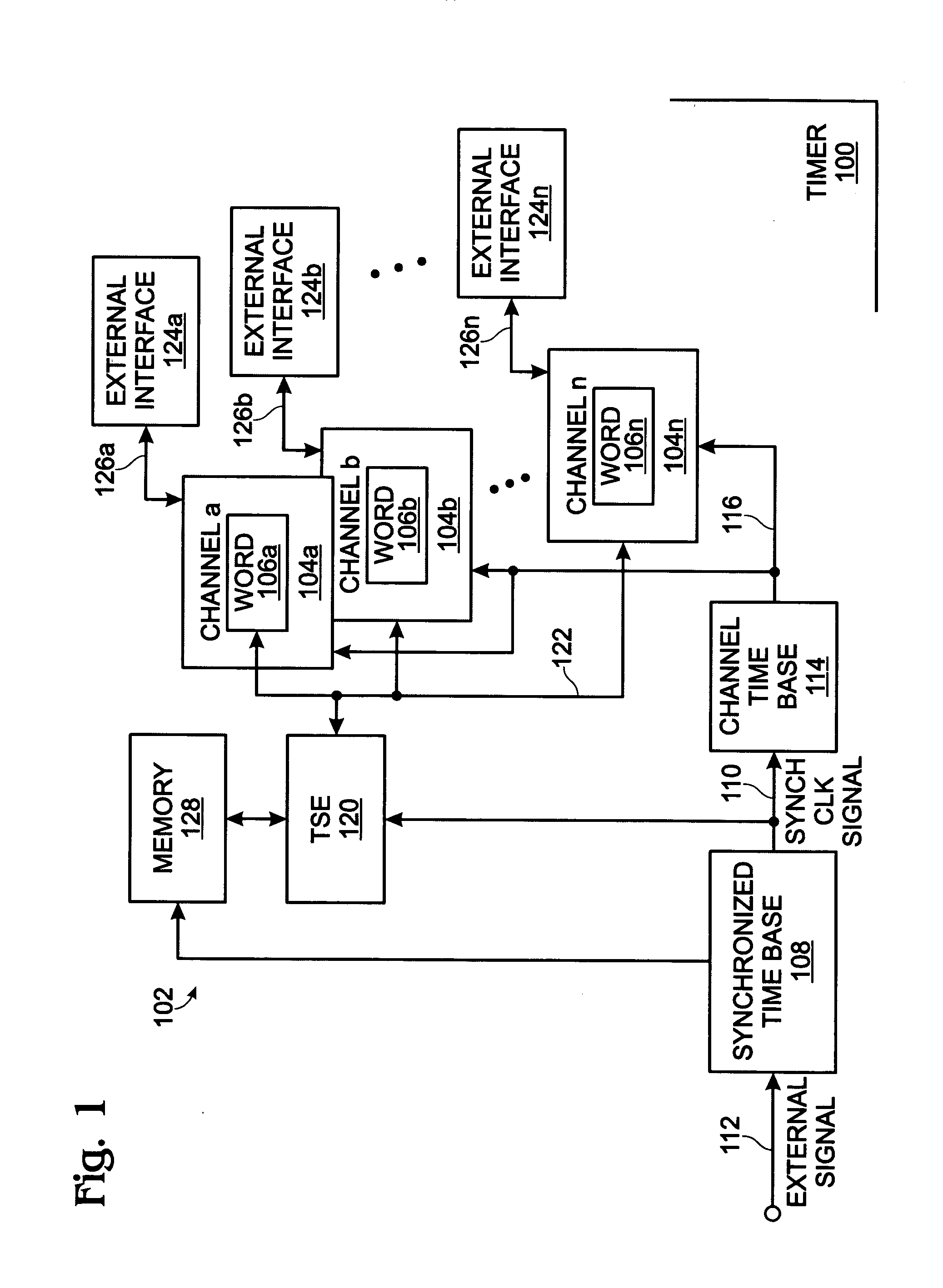
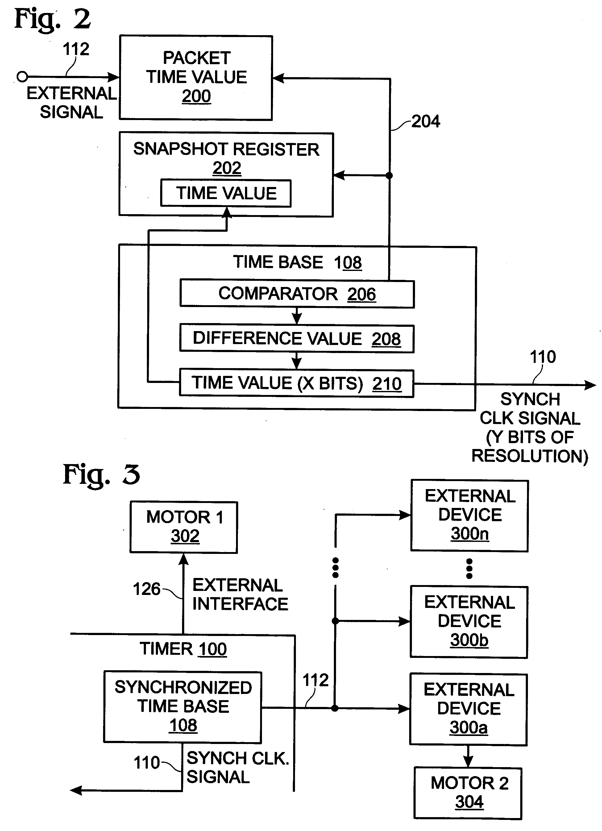
[0012]The present invention describes a timer whose channel time base can be synchronized to an external source, such as network-connected source. Network-synchronized programmable timer functions permit a user to distribute conventional timer functions across multiple devices with a high level of accuracy. Input capturing and output generation, for example, can be coordinated between multiple devices using independent clocking sources with a timing accuracy limited only by the hardware implementation.

Problems solved by technology

However, the microprocessor consumes system resources.
Further, the latency associated with microprocessors and software instructions is much greater than hardware logic operations.
Even more critical, the cost of designing the software to run a microprocessor-based timer can be very high.
While the PC may be enabled to run the cooperating operations, using the PC's clock as the central time base, this method of operation may be an inefficient use of the PC.
Further, the latency associated with microprocessors and software instructions is much greater than hardware logic operations.
Even more critical, the cost of designing the software to run the PC in this manner can be very high.
In a distributed control system using multiple clocks, individual clocks tend to drift apart.
However, conventional timer cannot be synchronized to external sources such as IEEE 1588.

Method used


Image

  • Timer with network synchronized time base
  • Timer with network synchronized time base
  • Timer with network synchronized time base

Examples


Embodiment Construction

[0022]Various embodiments are now described with reference to the drawings. In the following description, for purposes of explanation, numerous specific details are set forth in order to provide a thorough understanding of one or more aspects. It may be evident, however, that such embodiment(s) may be practiced without these specific details. In other instances, well-known structures and devices are shown in block diagram form in order to facilitate describing these embodiments.

[0023]As used in this application, the terms “component,”“module,”“system,” and the like are intended to refer to a computer-related entity, either hardware, firmware, a combination of hardware and software, software, or software in execution. For example, a component may be, but is not limited to being, a process running on a processor, a processor, an object, an executable, a thread of execution, a program, and / or a computer. By way of illustration, both an application running on a computing device and the ...


PUM


Abstract

A system and method are provided for synchronizing a programmable timer time base and an external time signal. The method either accepts or supplies an external time signal (e.g., IEEE 1588) at an external interface, links a synchronized time base to the external time signal, and clocks a channel time base with the synchronized time base. Then, a timer channel can be used to perform programmable timer functions in response to the channel time base. Some programmable timer functions include input capture, output compare, quadrature decoding, pulse measurement, frequency measurement, and pulse width modulation (PWM) functions. In one aspect, accepting the external time signal at the external interface includes detecting a packet with a time value. In another aspect, the method uses the channel to detect an event at a channel external interface, and compares the channel time base counter value with an expected value to modify the synchronized time base.

Description

BACKGROUND OF THE INVENTION[0001]1. Field of the Invention[0002]This invention generally relates to an electrical programmable event timer and, more particularly, to a timer that can be synchronized to operate with an external or network-derived time base.[0003]2. Description of the Related Art[0004]Programmable timers are widely used in the data processing and machine control fields. Some of the common tasks performed by most timers include input capture and output compare. An input capture function records (“captures”) the time at which an external event (electrical signal) occurs. For example, input capture may be used to read a limit switch or a temperature. An output compare function generates an output signal in response to programmed time intervals. For example, output compare can be used to run an electrical motor or solenoid. Input capture and output compare functions can be modified in response to commands from an associated programmable logic controller (PLC), programmabl...

Claims


Application Information

Patent Timeline
IPC IPC(8): H04J3/06
CPCH04J3/0685
Inventor LATREMOUILLE, DAMIEN
Owner MACOM CONNECTIVITY SOLUTIONS LLC
Learn More