Q-switched cavity dumped laser array

a laser array and cavity-dumped technology, applied in the field of optical systems, can solve the problems of not being able to produce pulses shorter than 200 ps, limiting the size of the gain medium and hence the energy and power delivered by the laser, and not being able to tight control the laser operation. , to achieve the effect of efficient power or energy scaling, fast response time and high energy

Inactive Publication Date: 2007-12-06
ZUCKER OVED
View PDF16 Cites 11 Cited by
  • Summary
  • Abstract
  • Description
  • Claims
  • Application Information

AI Technical Summary

Benefits of technology

[0007]A microchip, Q-switched, cavity-dumped laser array is disclosed. Each laser in the array is end-pumped by VCSEL and comprises an electro-optic Q-switch mechanism actively controlled by photoconductive switches. The fast response time of the system and its small dimension pr...

Problems solved by technology

However, this technique does not allow tight control of laser operation, such as repetition rate.
Moreover, to obtain pulses less than 100 ps, an extremely short cavity must be employed, which limits the size of the gain medium and hence the energy and power delivered by the laser.
This technique, however, generally does not produce pulses shorter than 200 ps and is not well suited for use in the...

Method used


Image

  • Q-switched cavity dumped laser array
  • Q-switched cavity dumped laser array
  • Q-switched cavity dumped laser array

Examples


Embodiment Construction

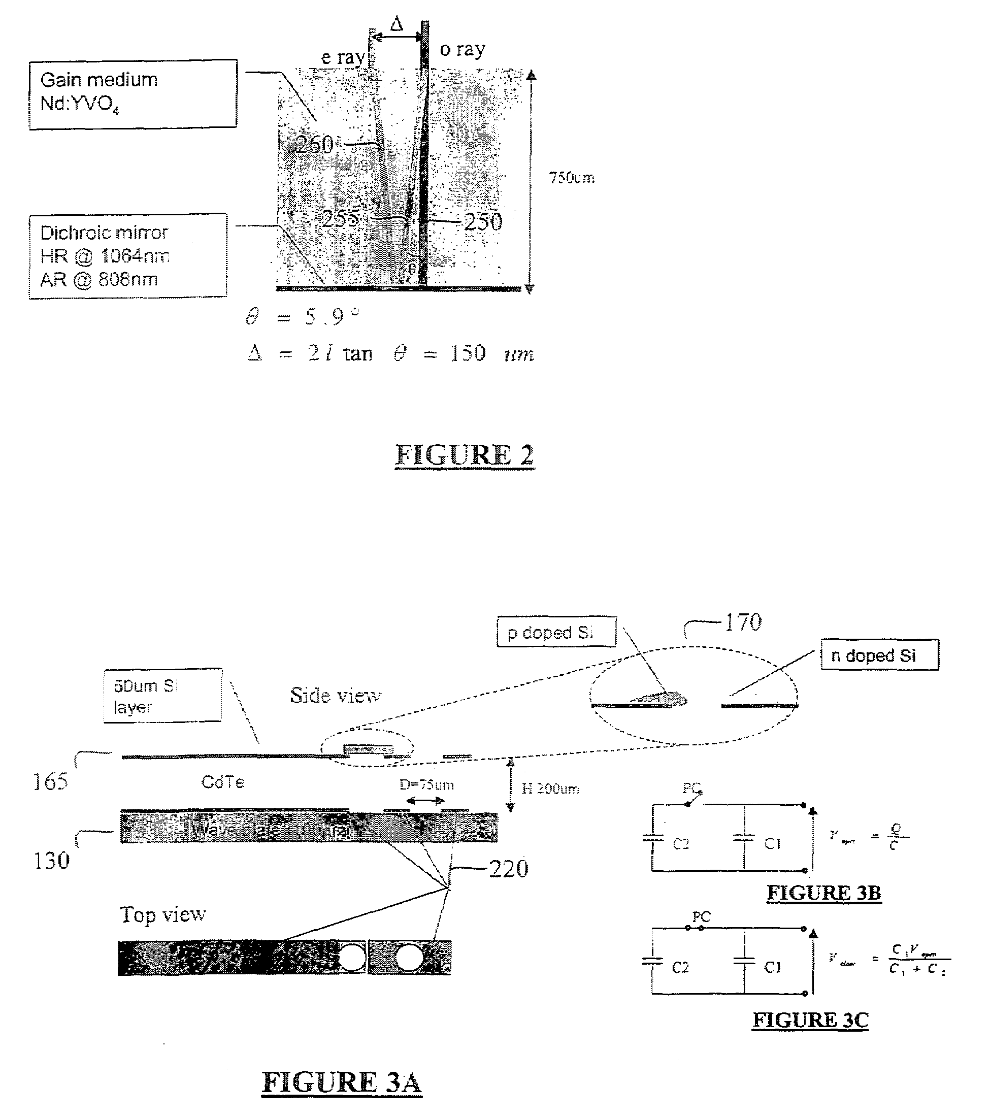
[0017]A microchip, Q-switched, cavity-dumped laser array is disclosed. Each laser in the array is end-pumped by VCSEL and comprises an electro-optic Q-switch mechanism actively controlled by photoconductive switches. The fast response time of the system and its small dimension produce short pulses (ten pico-second range), with high energy (uJ range). The microchip structure may be built using only planar, wafer-like components such that a high-density array of lasers may be manufactured without tight alignment tolerances, providing efficient power or energy scaling.

Laser Structure

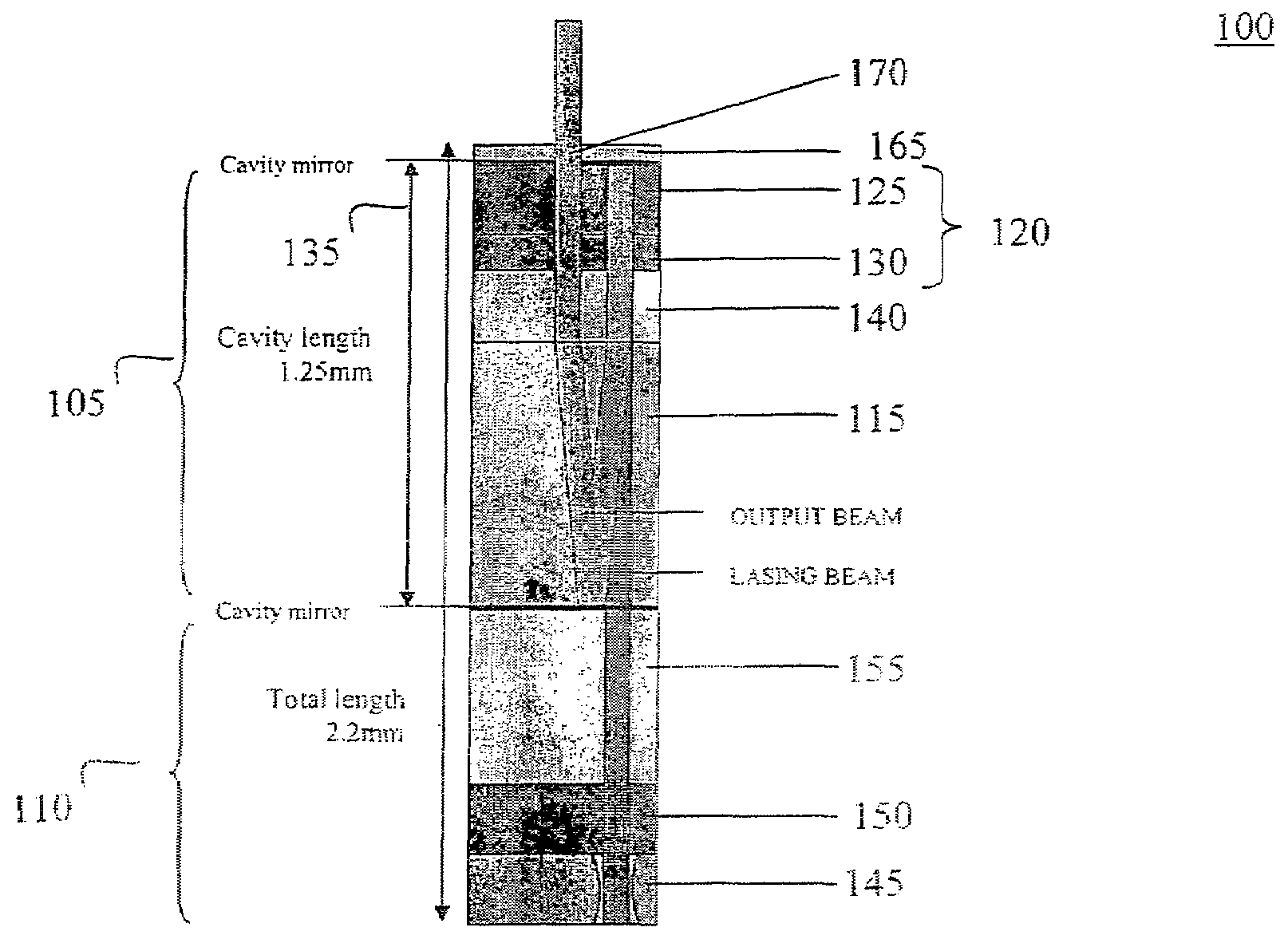
[0018]An illustrative laser structure according to an embodiment of the present invention is shown in FIG. 1A. Referring to FIG. 1A, the laser 100 includes a laser cavity section 105 and an optical pumping section 110. The laser cavity section 105 includes a lasing material layer 115, which may comprise any convenient lasing material, such as Nd:YVO4, a Pockels cell 120 and cavity mirrors 135 defining the l...


PUM


Abstract

A microchip, Q-switched, cavity-dumped laser is end-pumped by VCSEL or a laser diode and comprises an electro-optic Q-switch mechanism actively controlled by photoconductive switches. The fast response time of the system and its small dimension produce short pulses (ten pico-second range), with high energy (uJ range). The microchip structure may be built using planar, wafer-like components such that a high-density array of lasers may be manufactured without tight alignment tolerances, providing efficient power or energy scaling.

Description

FIELD OF THE INVENTION[0001]The present invention relates to optical systems and, more particularly, relates to Q-switched lasers arrays that are capable of cavity dumping and that lend themselves to being built in a compact array format.BACKGROUND OF THE INVENTION[0002]Microchip lasers are of great interest due to their compact size, ease of fabrication, high beam quality and use in communications, monitoring and other applications. Examples of microchip lasers and various architectures for operating in the longitudinal mode are given in the following U.S. Pat. No. 5,256,164 to Mooradian; U.S. Pat. No. 5,402,437 to Mooradian; U.S. Pat. No. 5,982,202 to Thony et al.; and U.S. Pat. No. 6,512,630 to Zayhowski. These references do not provide information on how to build an efficient Q-switched laser to produce short pulses, in the 100 pico-second range or less.[0003]Devices have been proposed to obtain pulsed microchip lasers using both passive and active Q-switching techniques. Passiv...

Claims


Application Information

Patent Timeline
IPC IPC(8): H01S3/115H01S3/11
CPCH01S3/0407H01S3/042H01S3/0602H01S3/0627H01S5/183H01S3/1103H01S3/115H01S3/1673H01S3/2383H01S3/09415
Inventor ZUCKER, OVED
Owner ZUCKER OVED
Why Eureka
Try Eureka