Electrically-pumped (Ga,In,Al)N vertical-cavity surface-emitting laser

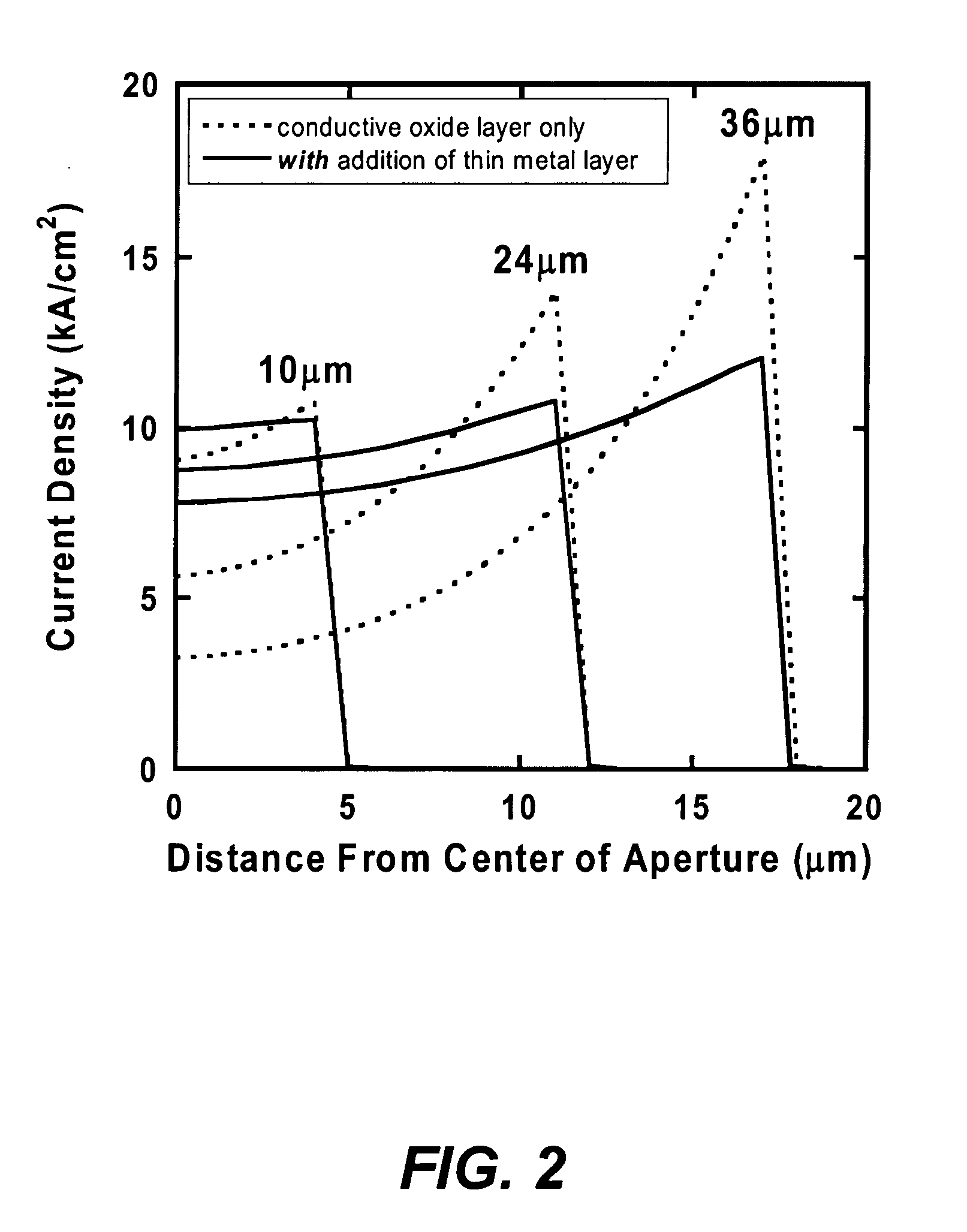
a laser and vertical cavity technology, applied in the direction of laser cooling arrangement, laser details, optical resonator shape and construction, etc., can solve the problems of limiting the practical and commercial utility, requiring either difficult fabrication techniques or difficult epitaxial growth, and achieves the effect of improving ohmic contact and lateral curren

Inactive Publication Date: 2007-12-06
RGT UNIV OF CALIFORNIA
View PDF3 Cites 289 Cited by
  • Summary
  • Abstract
  • Description
  • Claims
  • Application Information

AI Technical Summary

Benefits of technology

[0016] To overcome the limitations in the prior art described above, and to overcome other limitations that will become apparent upon reading and understanding the present specification, the present invention discloses a VCSEL comprising: a thin metal layer placed at an optical standing wave null within the cavity that provides for improved ohmic contact and lateral current distribution, a subs...

Problems solved by technology

These structures require the implementation of large and costly pumping lasers, which limits their practical and commercial utility.
However, they have not been successful and have required e...

Method used


Image

  • Electrically-pumped (Ga,In,Al)N vertical-cavity surface-emitting laser
  • Electrically-pumped (Ga,In,Al)N vertical-cavity surface-emitting laser
  • Electrically-pumped (Ga,In,Al)N vertical-cavity surface-emitting laser

Examples


Embodiment Construction

[0022] In the following description of the preferred embodiment, reference is made to the accompanying drawings which form a part hereof, and in which is shown by way of illustration a specific embodiment in which the invention may be practiced. It is to be understood that other embodiments may be utilized and structural changes may be made without departing from the scope of the present invention.

Overview

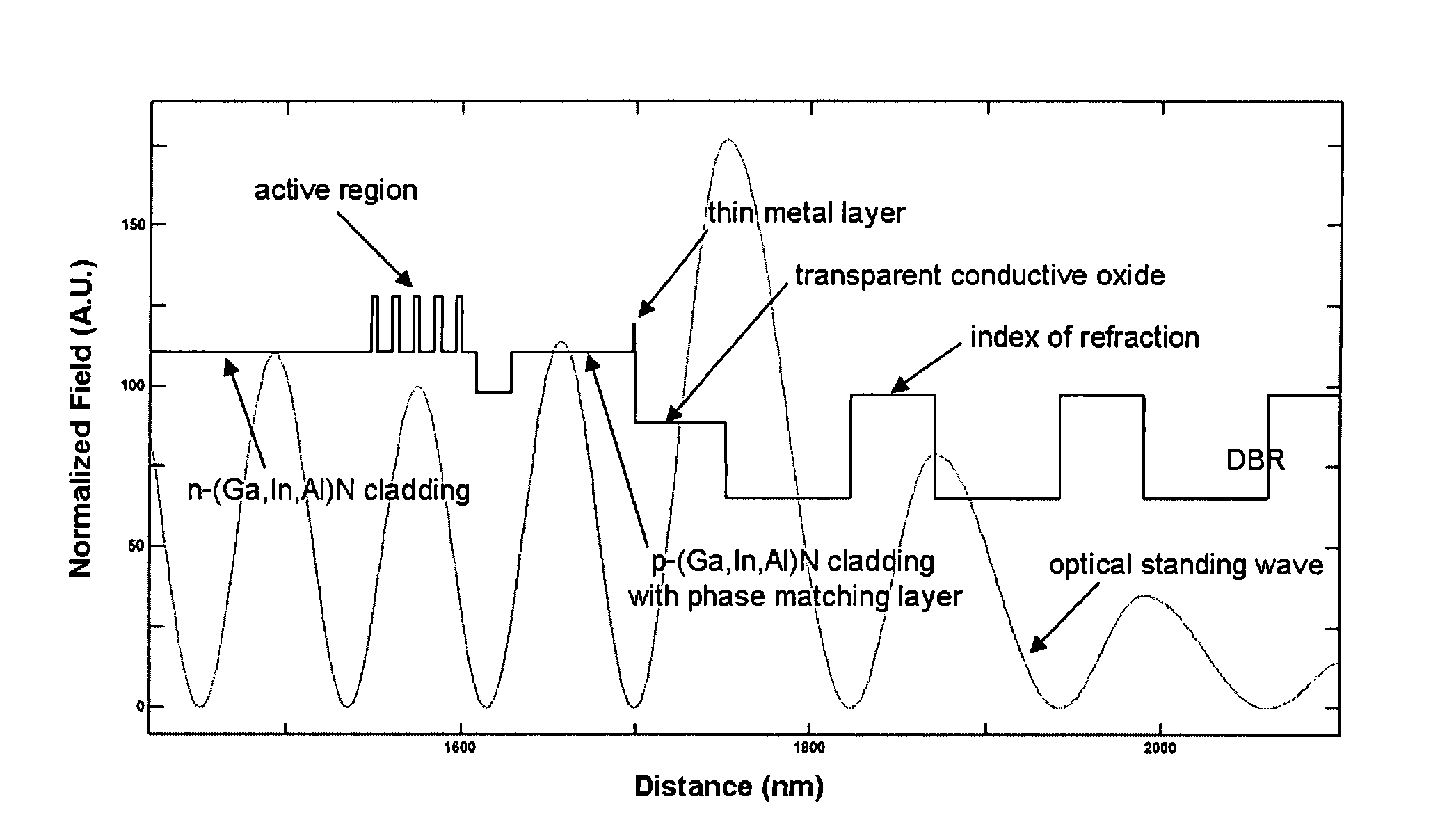
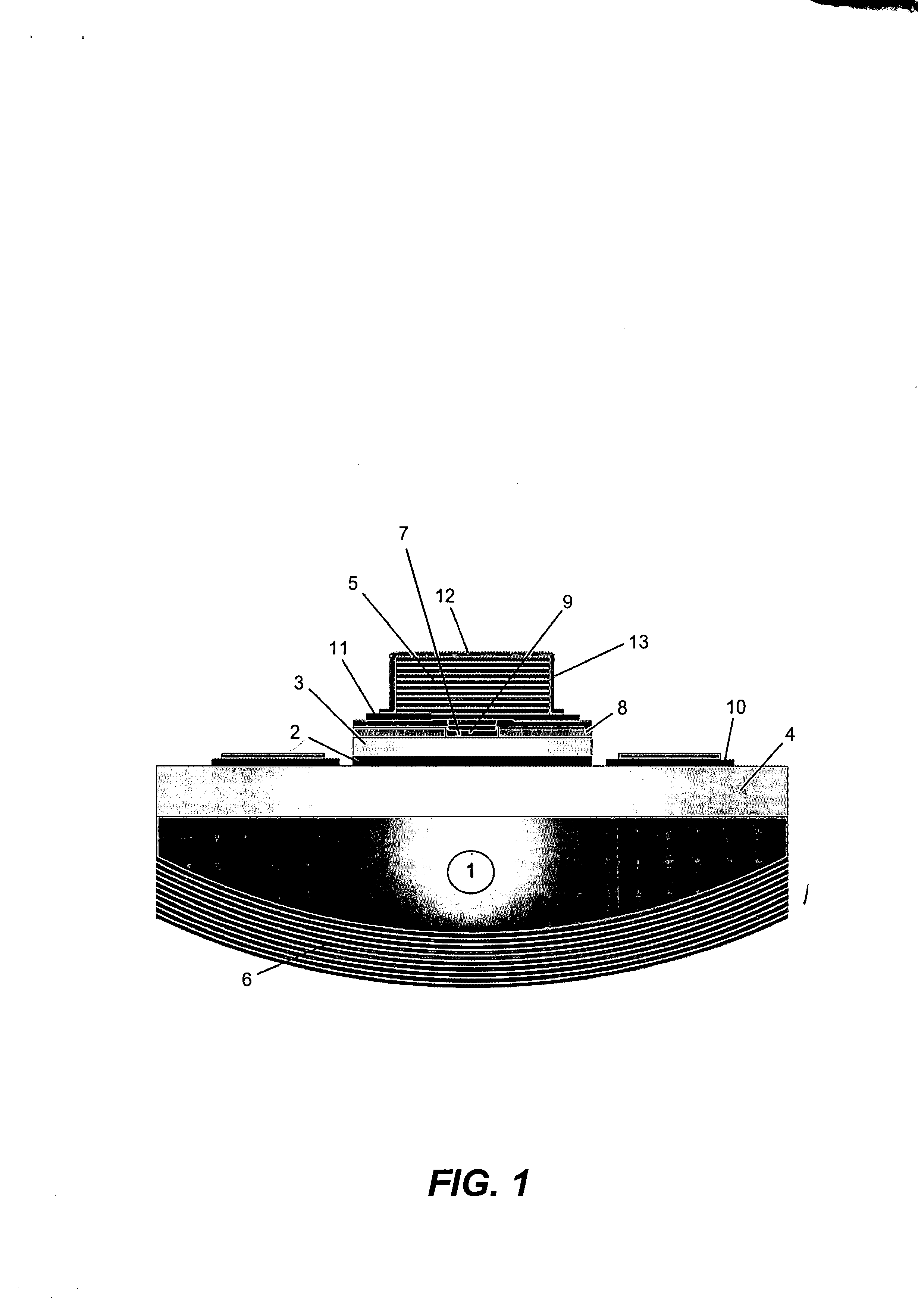
[0023] The present invention discloses a novel approach for producing monolithic green, blue, violet, or ultraviolet (UV) emitting VCSELs. The electrically-pumped device incorporates a substrate within an optical cavity and a plano-concave structure that is comprised of an epitaxially grown (Ga,In,Al)N base-structure with quantum wells, an integrated micromirror for control of the optical mode, and a thin metal intra-cavity contact and current aperture for improved ohmic contact and / or current distribution. The above elements are contained between two distributed Bragg reflector ...


PUM


Abstract

A vertical-cavity surface-emitting laser (VCSEL) comprising a low-loss thin metal contact and current spreading layer within the optical cavity that provides for improved ohmic contact and lateral current distribution, a substrate including a plano-concave optical cavity, a (Ga,In,Al)N multiple quantum well (MQW) active region contained within the optical cavity that generates light when injected by an electrical current, and an integrated micromirror fabricated onto the substrate that provides for optical mode control of the light generated by the active region. A relatively simple process is used to fabricate the VCSEL.

Description

CROSS-REFERENCE TO RELATED APPLICATIONS [0001] This application claims the benefit under 35 U.S.C. §119(e) of the following co-pending and commonly-assigned U.S. patent application: [0002] U.S. Provisional Patent Application Ser. No. 60 / 800,391, filed on May 15, 2006, by Daniel F. Feezell, Daniel A. Cohen, Robert M. Farrell, Masahiro Ishida and Shuji Nakamura, entitled “ELECTRICALLY PUMPED (Ga,In,Al)N VERTICAL-CAVITY SURFACE-EMITTING LASER,” attorneys docket number 30794.175-US-P1 (2006-419); [0003] which application is incorporated by reference herein. [0004] This application is related to the following co-pending and commonly-assigned applications: [0005] U.S. Utility application Ser. No. 11 / 067,957, filed Feb. 28, 2005, by Claude C. A. Weisbuch, Aurelien David, James S. Speck and Steven P. DenBaars, entitled “HORIZONTAL EMITTING, VERTICAL EMITTING, BEAM SHAPED. DISTRIBUTED FEEDBACK (DFB) LASERS BY GROWTH OVER A PATTERNED SUBSTRATE,” attorneys' docket number 30794.121-US-01 (2005-...

Claims


Application Information

Patent Timeline
IPC IPC(8): H01S5/00H01S3/04
CPCH01S5/0207H01S5/0421H01S5/0425H01S5/32341H01S5/18341H01S5/18388H01S5/18308H01S5/04257
Inventor FEEZELL, DANIEL F.COHEN, DANIEL A.FARRELL, ROBERT M.ISHIDA, MASAHIRONAKAMURA, SHUJI
Owner RGT UNIV OF CALIFORNIA
Why Eureka
Try Eureka