Phase shift based precoding method and transceiver for supporting the same
a precoding method and phase shift technology, applied in the direction of orthogonal multiplex, multiplex communication, diversity/multi-antenna system, etc., can solve the problems of difficult to obtain the above-described gains, high data transmission rate cannot be obtained, and codebook based precoding is not suitable for an environmen
- Summary
- Abstract
- Description
- Claims
- Application Information
AI Technical Summary
Benefits of technology
Problems solved by technology
Method used
Image
Examples
embodiment 1
Phase Shift Based Precoding Matrix
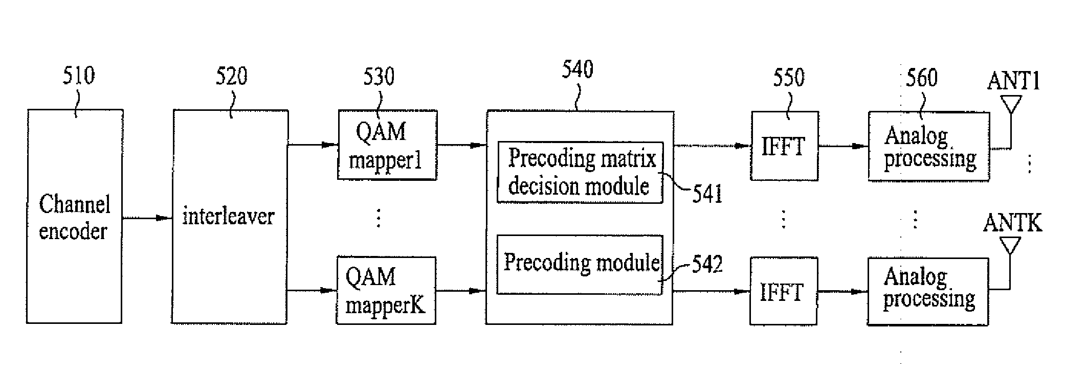
[0040]FIG. 5 is a block diagram showing the main configuration of a transceiver for performing a phase shift based proceding.
[0041] In the phase shift based precoding, all streams to be transmitted are via all antennas. And the streams are multiplied by different phase sequences. In general, when the phase sequence is generated using a small cyclic delay, a channel value increases or decreases according to a frequency domain while frequency selectivity occurs in the channel from the viewpoint of a receiver.
[0042] As shown in FIG. 5, a transmitter allocates a user terminal to a high frequency for stabilizing a channel state in a frequency band which fluctuates depending on a relatively small cyclic delay. Where, a phase shift based proceding matrix is used to apply a cyclic delay, which constantly increases or decreases, to each antenna.
[0043] The phase shift based proceding matrix P may be expressed by Equation 1. PNt×Rk=(w1,1kw1,2k…w1,Rkw2,1k...
embodiment 2
Generalized Phase Shift Diversity Matrix
[0054] The phase shift based precoding matrix described above may be expressed by Equation 12 with respect to a system in which the number of (physical or virtual) antennas Nt (Nt is a positive number of 2 or more) and the spatial multiplexing rate is R (R is a positive number of 1 or more). Since this equation is obtained by generalizing the conventional phase shift diversity, the multiple-antenna scheme expressed by Equation 12 is also called a generalized phase shift diversity (GPSD). GPSDNt×Rk=(w1,1kw1,2k…w1,Rkw2,1kw2,2k…w2,Rk⋮⋮⋰⋮wNt,1kwNt,2k…wNt,Rk)=(ⅇjθ1k0…00ⅇjθ2k…0⋮⋮⋰0000ⅇjθNtk)(UNt×Rk)Equation 12
where, GPSDN, ×Rk denotes a GPSD matrix of a kth subband or subcarrier of an MIMO-OFDM signal having a spatial multiplexing rate R and Nt transmission (physical or virtual) antennas and UN, ×R denotes a unitary matrix satisfying UN, ×RH×UN, ×R=IR×R which is used to minimize the inter-symbol interference of the subcarrier corresponding...
embodiment 3
Generalized Time-varying Phase Shift Diversity
[0065] In the GPSD matrixes of Equations 12, 14 and 15, the phase angle θi of the diagonal matrix and / or the unitary matrix U may vary with time. For example, a time-varying GPSD of Equation 12 may be expressed by Equation 18. GPSDNt×Rk(t)=(ⅇj θ1(t)k0…00ⅇj θ2(t)k…0⋮⋮⋰0000ⅇj θNt(t)k)(UNt×R(t))Equation 18
where, GPSDN, ×Rk(t) denotes a GPSD matrix of a kth subcarrier or subband of an MIMO-OFDM having a spatial multiplexing rate of R and Nt transmission (physical or virtual) antennas at a specific time t and UN, ×R(t) denotes a unitary matrix (fourth matrix) for satisfying UN, ×RH×UN, ×R=R×R which is used to minimize the inter-symbol interference of the subcarrier corresponding to each antenna. In particular, in order to maintain the unitary matrix characteristics of a diagonal matrix (third matrix) for phase shift, it is preferable that UN, ×R(t) satisfies the condition of the unitary matrix. In Equation 18, a relations...
PUM
 Abstract
Description
Claims
Application Information
 - R&D
- Intellectual Property
- Life Sciences
- Materials
- Tech Scout
- Unparalleled Data Quality
- Higher Quality Content
- 60% Fewer Hallucinations
Browse by: Latest US Patents, China's latest patents, Technical Efficacy Thesaurus, Application Domain, Technology Topic, Popular Technical Reports.
© 2025 PatSnap. All rights reserved.Legal|Privacy policy|Modern Slavery Act Transparency Statement|Sitemap|About US| Contact US: help@patsnap.com


