

Combination hydrodynamic and rolling bearing system
a technology of hydrodynamic and rolling bearings, applied in the direction of machines/engines, bearing unit rigid support, liquid fuel engines, etc., can solve the problems of reducing the overall efficiency of the turbocharger, and the failure of ball bearings when used in the turbocharger assembly
- Summary
- Abstract
- Description
- Claims
- Application Information
AI Technical Summary
Benefits of technology
Problems solved by technology
Method used
Image

Examples
Embodiment Construction
[0014] The following description of the preferred embodiment(s) is merely exemplary in nature and is in no way intended to limit the invention, its application, or uses.
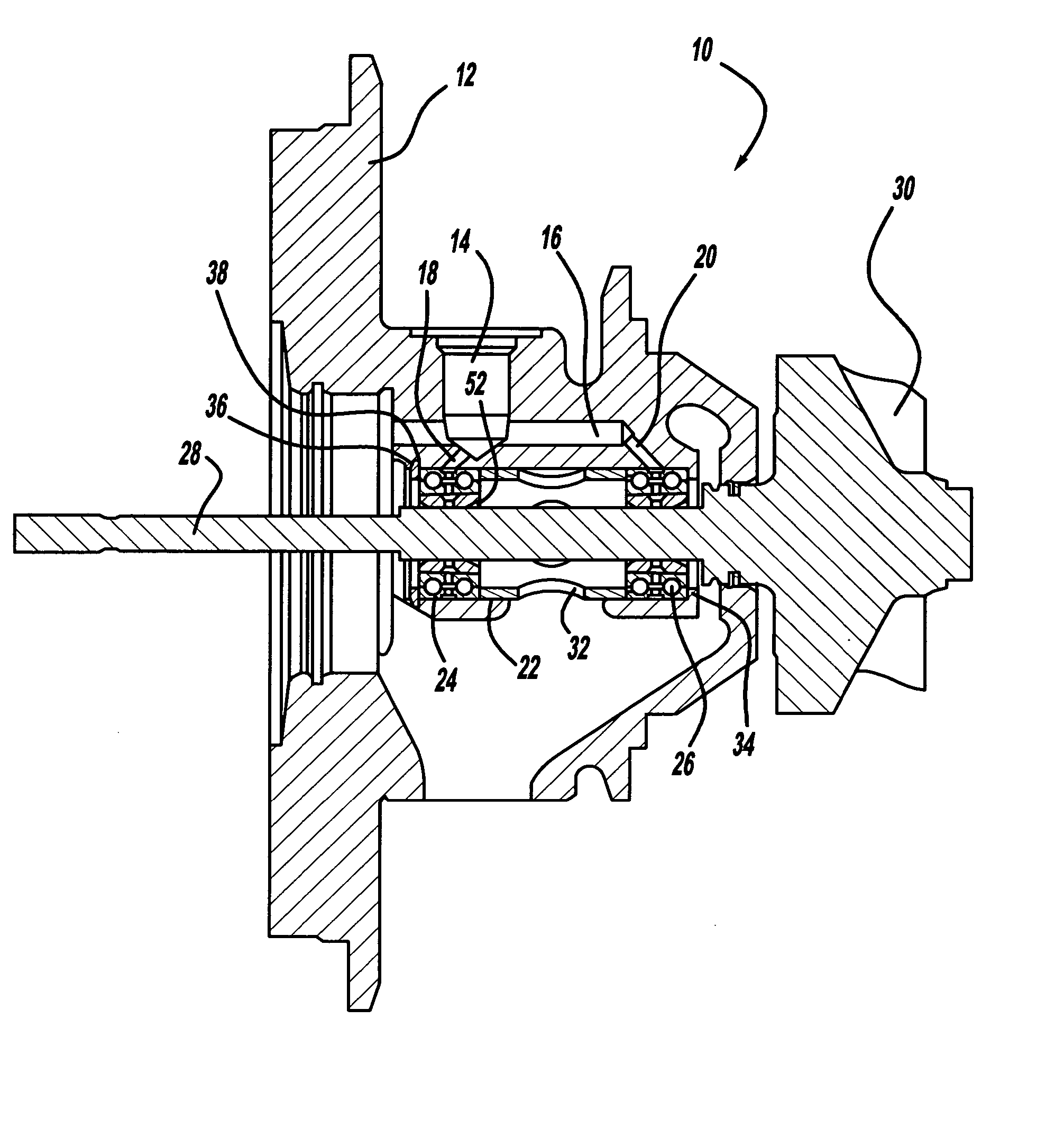
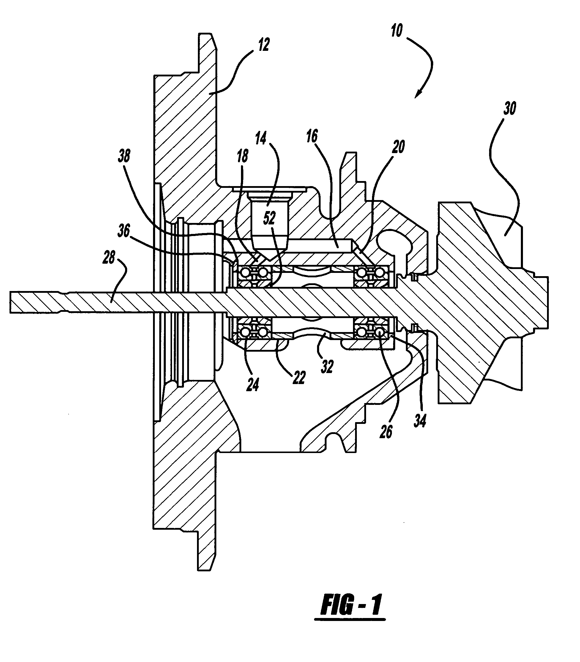
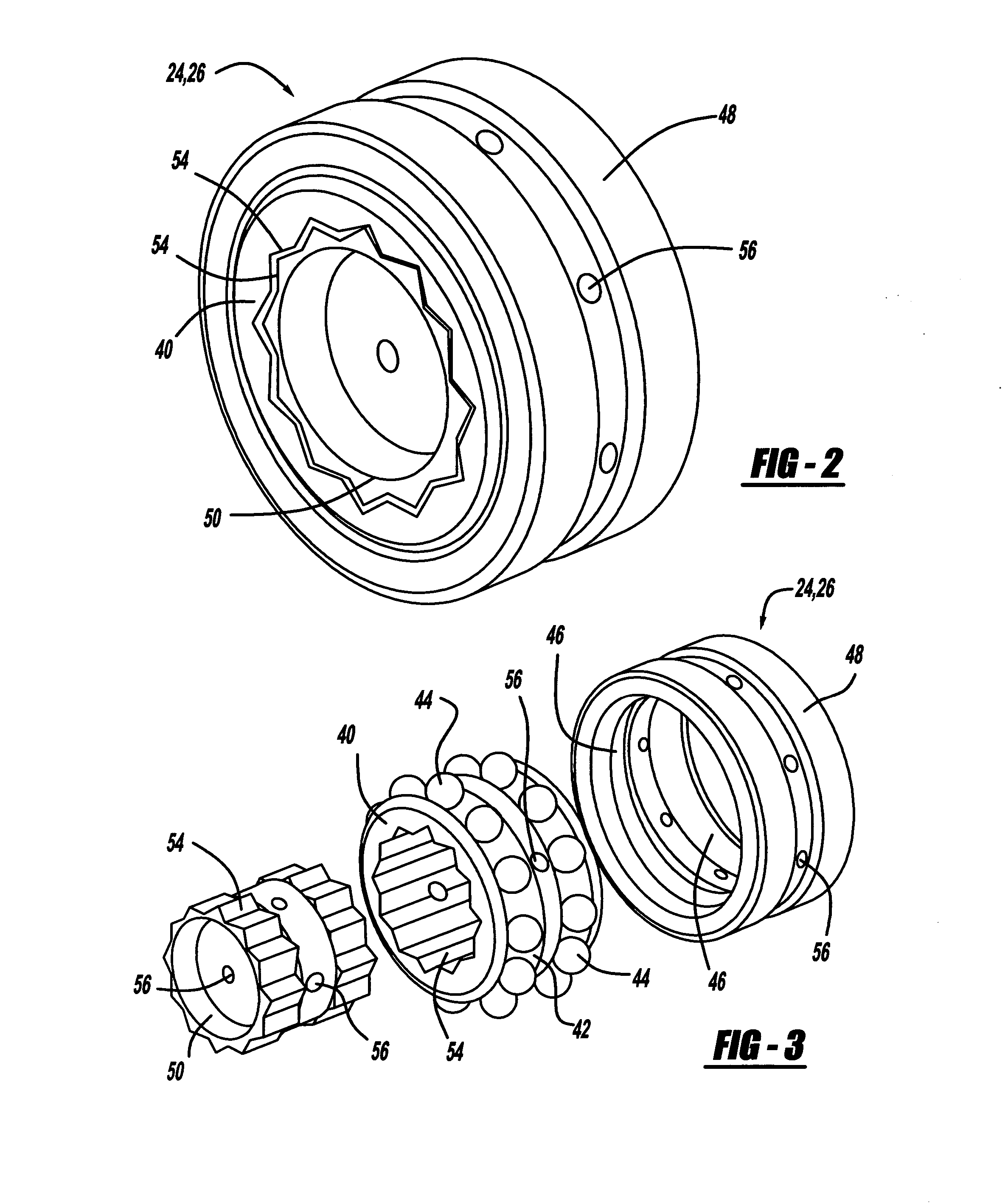
[0015] Referring to FIG. 1, a portion of a turbocharger unit 10 is shown. The turbocharger unit 10 includes an intermediate housing 12 having various bores, ports, and openings to accommodate the components of the turbocharger unit 10. The intermediate housing 12 has a main oil inlet 14, which has a primary oil passageway 16, and two secondary oil passageways 18, 20. The secondary oil passageways 18, 20 lead into a bore 22. The bore 22 is used to support first hybrid bearing 24 and second hybrid bearing 26; first hybrid bearing 24 and second hybrid bearing 26 are used to support a shaft 28 having a turbine wheel 30. Connected to the intermediate housing 12 and surrounding the turbine wheel 30 is a turbine housing (not shown). Also mounted on the shaft 28 at the opposite end of the turbine wheel 30 is a compressor wh...
PUM
 Abstract
Description
Claims
Application Information