

Axial fan assembly
- Summary
- Abstract
- Description
- Claims
- Application Information
AI Technical Summary
Benefits of technology
Problems solved by technology
Method used
Image

Examples
Embodiment Construction
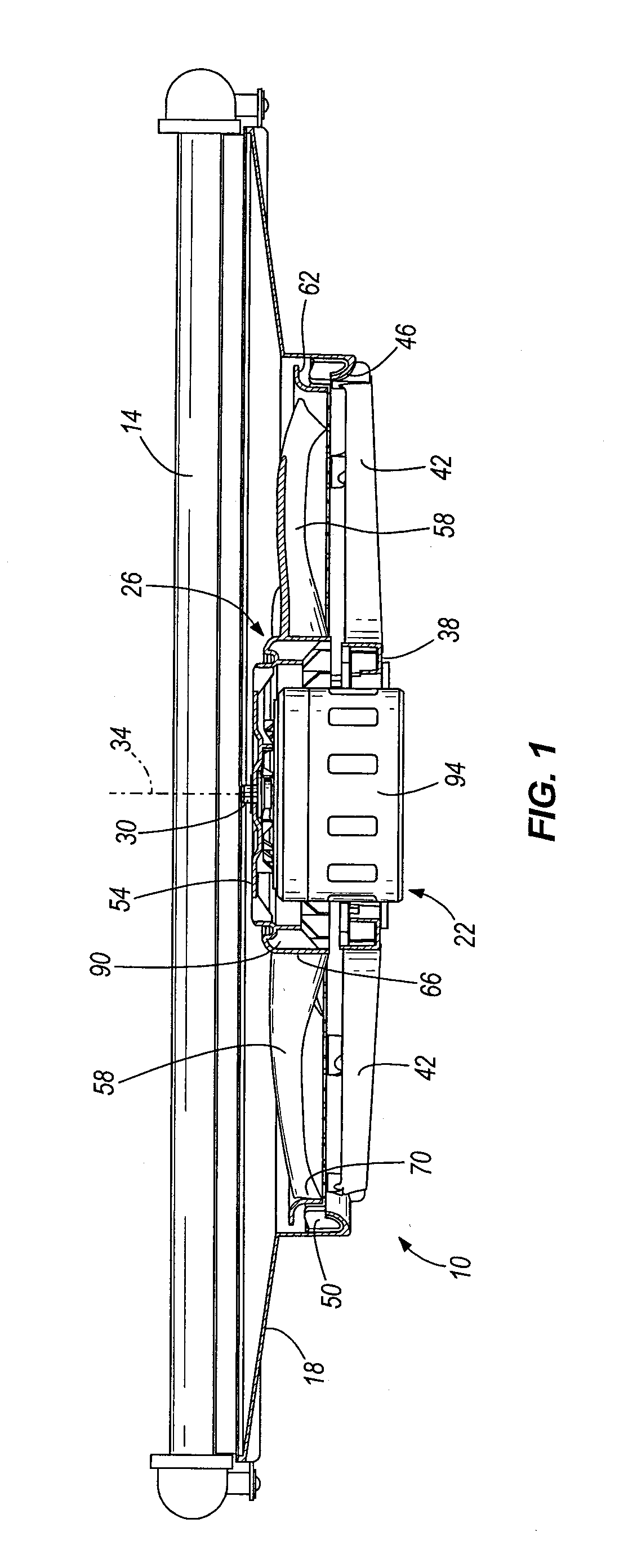
[0020]FIG. 1 illustrates an axial fan assembly 10 coupled to a heat exchanger 14, such as an automobile radiator. However, the axial fan assembly 10 may be utilized in combination with the heat exchanger 14 in any of a number of different applications. The axial fan assembly 10 includes a shroud 18, a motor 22 coupled to the shroud 18, and an axial fan 26 coupled to and driven by the motor 22. Particularly, as shown in FIG. 1, the motor 22 includes an output shaft 30 for driving the axial fan 26 about a central axis 34 of the output shaft 30 and the axial fan 26.
[0021]The axial fan assembly 10 is coupled to the heat exchanger 14 in a “draw-through” configuration, such that the axial fan 26 draws an airflow through the heat exchanger 14. Alternatively, the axial fan assembly 10 may be coupled to the heat exchanger 14 in a “push-through” configuration, such that the axial fan 10 discharges an airflow through the heat exchanger 14. Any of a number of different connectors may be utilize...
PUM
 Abstract
Description
Claims
Application Information