
Fuel Release Management For Fuel Cell Systems

Inactive Publication Date: 2007-12-06
FORD MOTOR CO +1
View PDF9 Cites 20 Cited by
  • Summary
  • Abstract
  • Description
  • Claims
  • Application Information

AI Technical Summary

Benefits of technology

[0002] The invention relates to methods and systems for improved management of fuel releases from fuel cell systems, and, more

Problems solved by technology

Nonetheless, simply venting the anode exhaust into the environment may not be acceptable: this wastes hydrogen fuel and venting hydrogen-containing exhaust may not be tolerated in certain applications.
In closed systems, generally, the concentration of any impurities present in the hydrogen stream supplied to the stack will increase over time; this can have adverse effects on fuel cell performance.
Fuel cell performance decreases over time as the concentration of inert gases increases, and can lead to cell failure if fuel starvation conditions develop.
In power plants where pressurized air is supplied to the stack this problem is further exacerbated by the corresponding increased permeation rate of inert gas across the membrane.
In addition, as water vapor accumulates in the anode flow fields liquid water can condense, which may result in flooding of the fuel cell.
Fuel leakage or release may occur unintentionally or intentionally during normal operation of a PEM fuel cell.
Combustion of fuel and oxidant may occur if the fuel releases are not controlled.
One disadvantage with systems such as that in U.S. 2003 / 77488 is that the system deals only with intentional releases, i.e., only those from the purge system, and provides no means of addressing other releases, such as unintentional releases that may occur from, for example, seal leaks or other parts of the fuel cell system.
In addition, devices such as the fuel diluter of U.S. 2003 / 77488 may be susceptible to external ignition, such as from a spark.
Such an arrangement is problematic in that as each of the fuel and oxidant inlet and outlet manifolds are intentionally sealed off from the interior of the housing, any leaks from the system will build up inside the enclosure.
A significant disadvantage of systems such as those proposed in U.S. Pat. Nos. 5,856,034 and 6,455,183 is that there is no assurance that the fuel will be adequately mixed with the air.
There is a risk of “short-circuiting” in such systems, for example a fuel release may pass directly to the cathode before mixing can occur.
Thus, local fuel releases may be in close proximity to a catalytic ignition source, but cannot be completely mixed and diluted with the incoming air before contacting the cathode catalyst.
Accordingly, there is a risk that a local fuel release will be mixed only with local ventilation air or only a small portion of the incoming air, and may result in a flammable mixture reaching the catalyst.
This may produce ignition, propagation of a flame back to the point of the release, high local heat generation and / or damage to or failure of the system.
In other instances, incomplete mixing of the fuel with only a small portion of the incoming air may allow non-uniform fuel / oxidant mixtures that could exceed the flammability limits to collect in local spots within the enclosure.
If such non-uniform fuel / oxidant mixtures reach the cathode without further mixing or dilution, they may lead to local temperature increases at the cathode catalyst.
These “hotspots” may result in sintering of the catalyst, loss of activity or damage to the catalyst structure.

Method used


Image

  • Fuel Release Management For Fuel Cell Systems
  • Fuel Release Management For Fuel Cell Systems
  • Fuel Release Management For Fuel Cell Systems

Examples


Embodiment Construction

[0025] In the following detailed description, certain specific details are set forth in order to provide a thorough understanding of various embodiments of the invention. However, one skilled in the art will understand that the invention may be practiced without these details. In other instances, well known structures associated with fuel cell stacks and fuel cell systems including, but not limited to, control systems including microprocessors have not been described in detail to avoid unnecessarily obscuring the descriptions of the embodiments of the invention.

[0026] Unless the context requires otherwise, throughout the specification and claims which follow, the word “comprise” and variations thereof, such as “comprises” and “comprising” are to be construed in an open, inclusive sense, that is as “including but not limited to”.

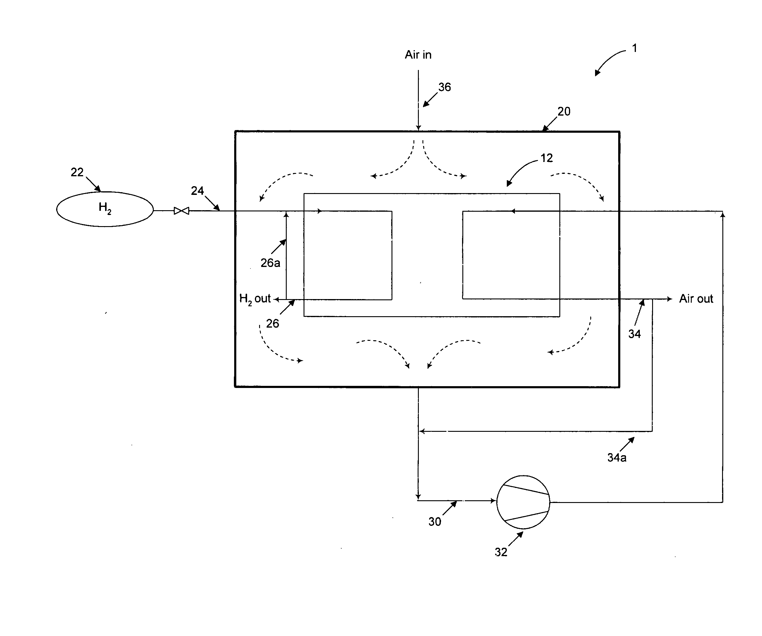
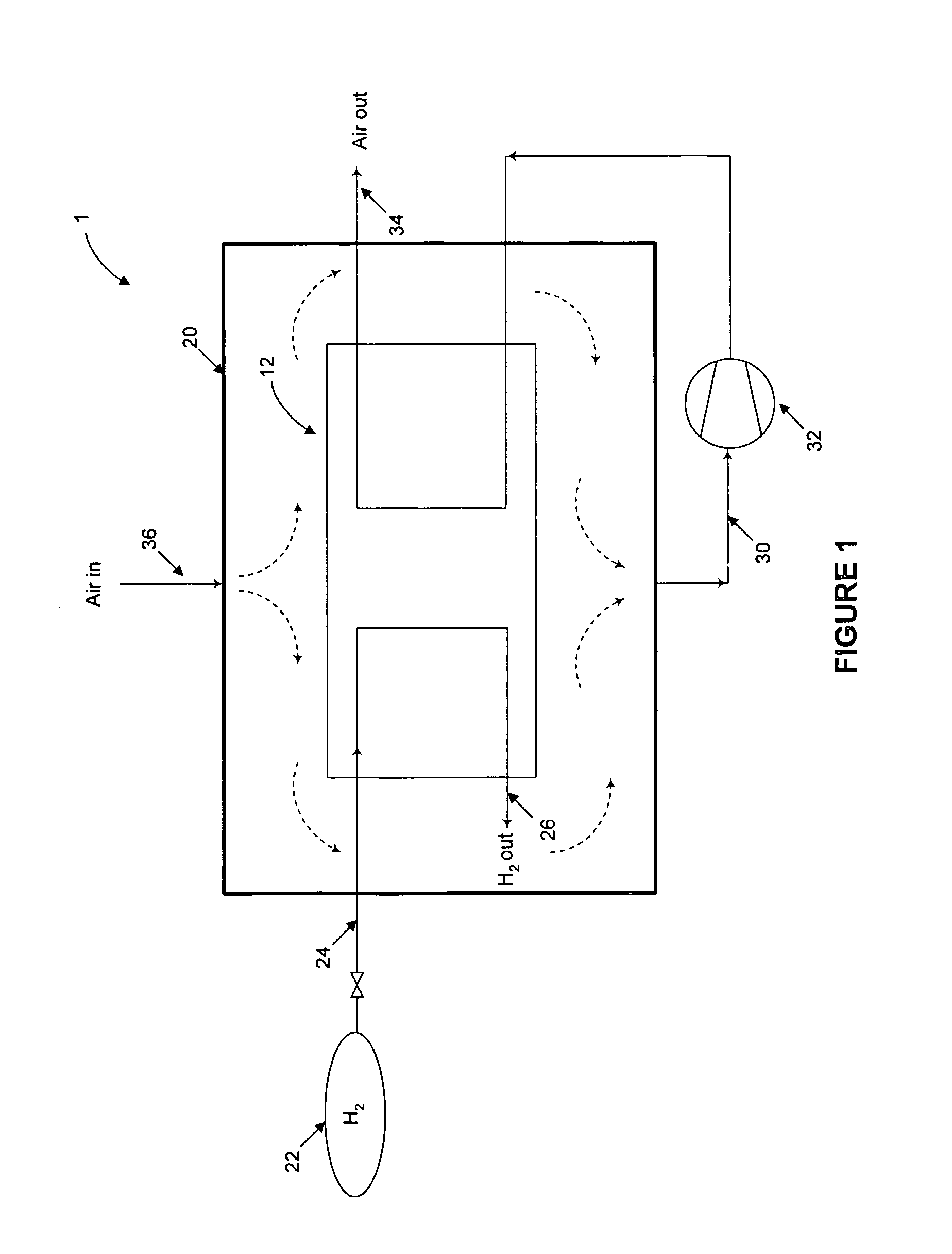
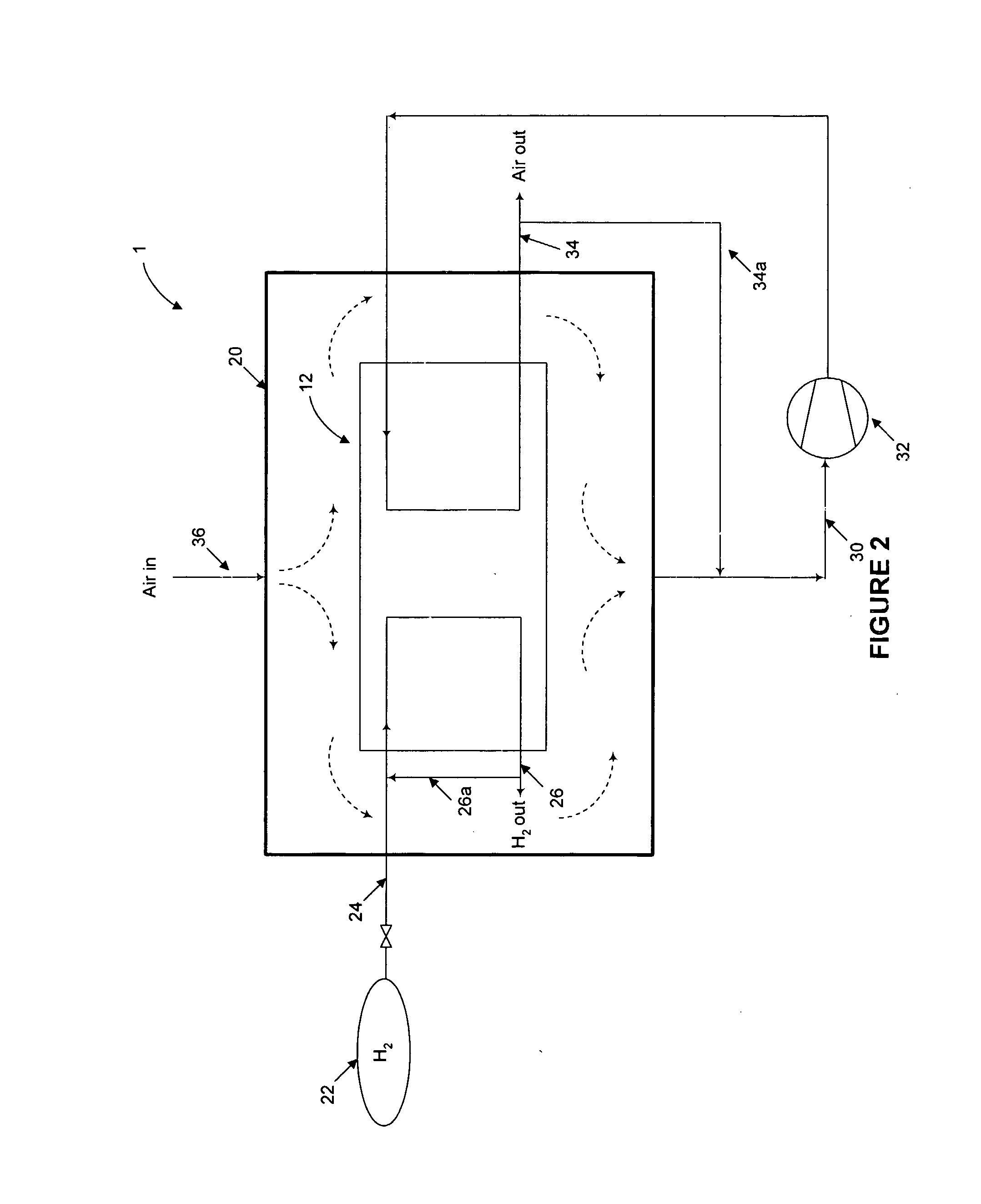
[0027] An exemplary fuel cell system 1 is shown schematically in FIG. 1. Fuel cell system 1 comprises a fuel cell stack 12, which is composed of at least o...


PUM


Abstract

Methods and apparatus for fuel release mitigation including enclosing a fuel cell stack (12) within an enclosure (20), supplying oxidant to the enclosure, circulating the oxidant within the enclosure to mix with any fuel present in the enclosure, withdrawing circulated oxidant from the enclosure; and supplying at least a portion of the circulated oxidant withdrawn from the enclosure to the stack as the cathode inlet stream.

Description

BACKGROUND OF THE INVENTION [0001] 1. Field of the Invention [0002] The invention relates to methods and systems for improved management of fuel releases from fuel cell systems, and, more particularly, to methods and systems employing oxidant delivery to mitigate the effect of fuel releases in fuel cell systems. [0003] 2. Description of the Prior Art [0004] Fuel cell systems are presently being developed for use as power supplies in a wide variety of applications, such as stationary power plants and portable power units. Such systems offer the promise of economically delivering power while providing environmental benefits. [0005] Fuel cells convert fuel and oxidant reactants to generate electric power and reaction products. Typical fuels include hydrogen and hydrocarbons such as natural gas, methanol or gasoline reformate, while suitable oxidants include air and oxygen. Fuel cells generally employ an electrolyte disposed between cathode and anode electrodes. A catalyst typically ind...

Claims


Application Information

Patent Timeline
IPC IPC(8): H01M8/04B03C3/74H01M8/24
CPCH01M8/04097Y02E60/50H01M8/2475H01M8/04231H01M8/04
Inventor SEDERQUIST, RICHARD A.BLASZCZYK, JANUSZPROCTER, MICHAEL J.FLECK, WOLFRAM
Owner FORD MOTOR CO
Learn More