
Efficient Application Of Reduced Variable Transformation And Conditional Stability Testing In Reservoir Simulation Flash Calculations

Active Publication Date: 2007-12-06
CHEVROU USA INC
View PDF0 Cites 27 Cited by
  • Summary
  • Abstract
  • Description
  • Claims
  • Application Information

AI Technical Summary

Benefits of technology

[0013] It is an object of the present invention to provide a more reliable reduced-variable phase-split algorithm by selecting primary variables corresponding to the least abundant phase present;
[0014] It is another object to use a bounded interval to limit solution changes in the reduced variable algorithms (phase split and stability) to achieve greater stability of the algorithms and / or avoid excessive iterations.
[0015] It is yet another object to provide an enhanced method for performing stability tests using reduced variables by employing a direct residual form based on the definition of the reduced variables and the tangent-plane distance condition.

Problems solved by technology

This calculation fundamentally involves finding the minimum of a thermodynamic state function (the Gibbs Free Energy (GFE), and as such is iterative in nature and frequently difficult to converge and computationally expensive, particularly when detailed fluid models are used, i.e., when there are many hydrocarbon components present.
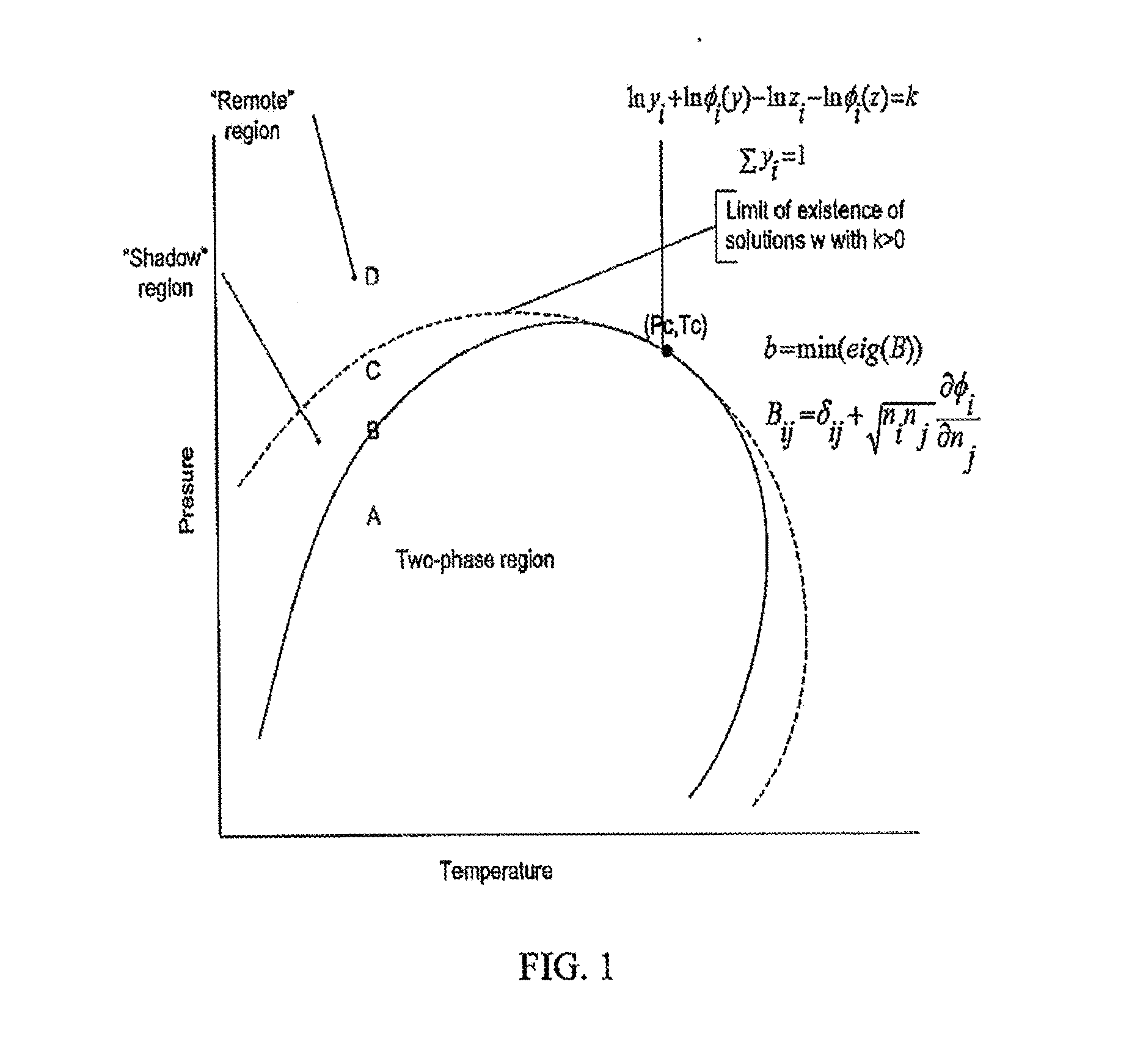
Also, the particular stability algorithm, as formulated, may experience convergence difficulties, particularly when encountering conditions far into the undersaturated zone.
In addition, the split algorithm is formulated in terms of the vapor phase and will exhibit numerical and / or convergence difficulties near dew-points, due to the virtually non-existent liquid phase.

Method used


Image

  • Efficient Application Of Reduced Variable Transformation And Conditional Stability Testing In Reservoir Simulation Flash Calculations
  • Efficient Application Of Reduced Variable Transformation And Conditional Stability Testing In Reservoir Simulation Flash Calculations
  • Efficient Application Of Reduced Variable Transformation And Conditional Stability Testing In Reservoir Simulation Flash Calculations

Examples


Embodiment Construction

[0024] The following nomenclature shall be used with the equations that follow:

SymbolsD =Tangent Plane Distance (TPD)G =Gibbs Free Energy function (GFE)c =Number of hydrocarbon componentsm =Number of non-zero Eigen valuesM =Number of reduced parameters. Equalsm+1P =PressureQ =Reduced variables (M-vector) of entriesQαQ =Reduction coefficients matrix of sizeMc of entriesqijR =Universal Gas ConstantT =Temperaturex =Liquid phase composition (mole fractions)y =Vapor phase composition (mole fractions)Y =Unnormalized moles of trial phasez =Feed (total) composition (mole fractions)Subscriptsi, j =Component indexα =Reduced variable indexL =LiquidV =VaporSuperscriptsF =Feed phaseT =Trial phaseGreek symbolsφi =Fugacity coefficientδij =Binary interaction coefficients (BIC)

[0025] The teachings of Firoozabadi, A. and Pan, H., Fast and Robust Algorithm for Compositional Modeling Part I—Stability Analysis, SPE 63083 and Firoozabadi, A. and Pan, H., Fast and Robust Algorithm for Compositional Mode...


PUM


Abstract

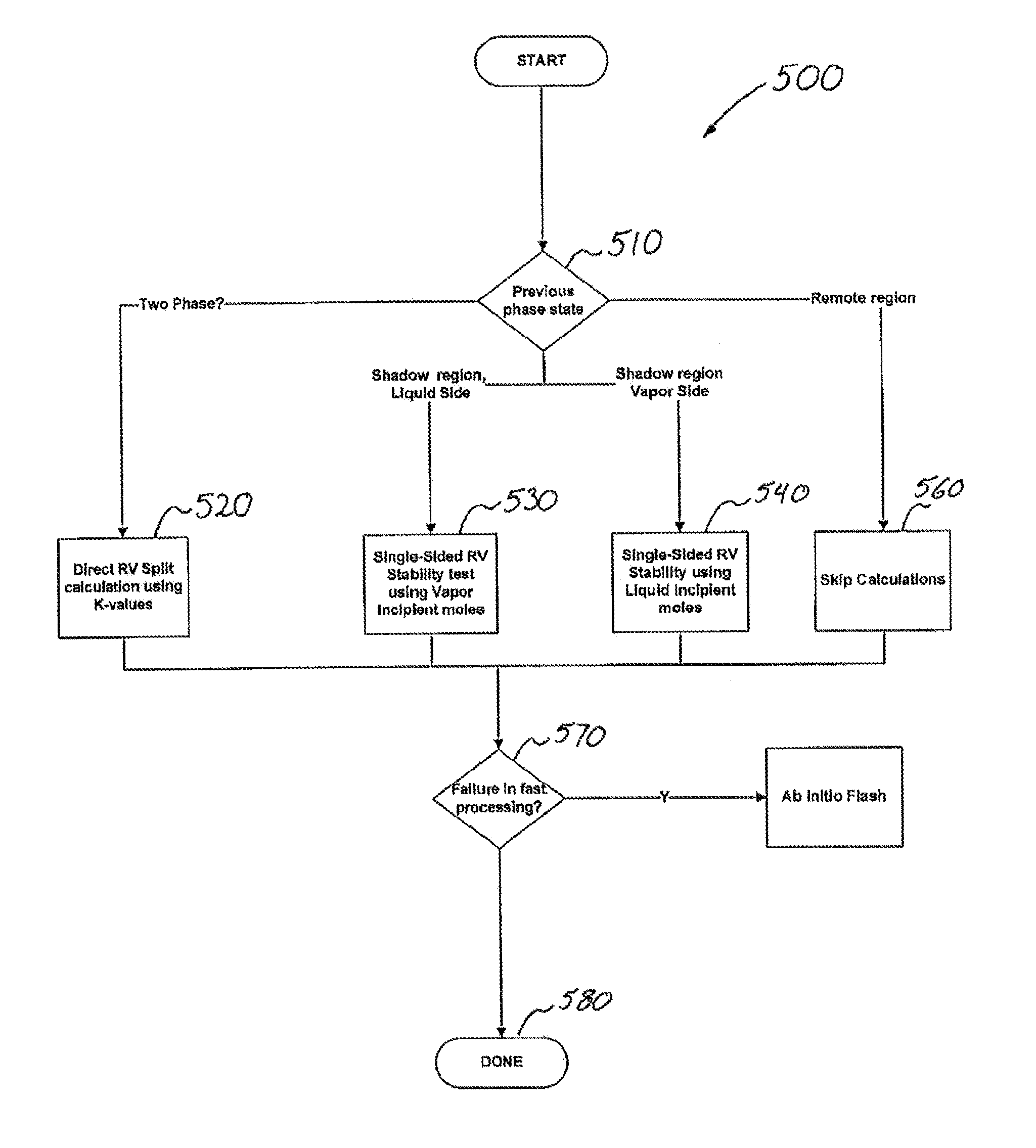
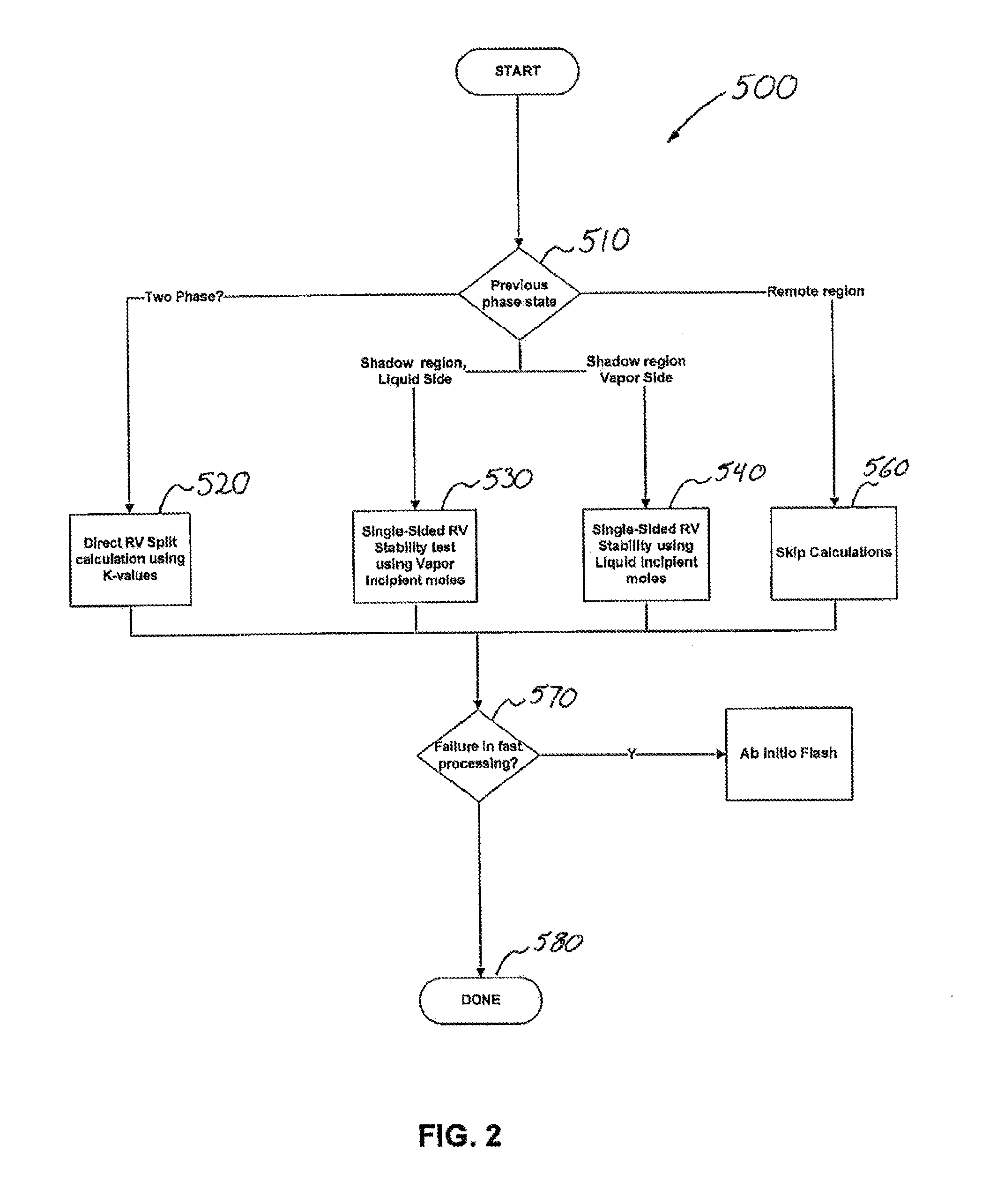
Methods and computer readable media for performing a compositional reservoir simulation of a subterranean hydrocarbon-bearing reservoir is provided. Reduced variables for flash computations are utilized with a methodology of conditional stability testing for achieving optimal efficiency of phase behavior computations in a compositional reservoir simulator. A least abundant phase is selected as primary variables for a primary phase and a secondary phase is selected for a more abundant phase to ensure stability by not dividing by a value near zero due to the selection of the primary phase as being associated with phase which is the least abundant. A bounded interval may be used to limit solution changes in reduced variable algorithms to achieve greater stability of algorithms. Stability tests may be performed during flash computations using reduced variables by employing a direct residual form based on the definition of the reduced variables and the tangent-plane distance condition.

Description

RELATED APPLICATION [0001] This nonprovisional application claims the benefit of co-pending provisional patent application U.S. Ser. No. 60 / 811,642, filed on Jun. 6, 2006, which is hereby incorporated by reference in its entirety.TECHNICAL FIELD [0002] The present invention relates generally to computer enabled reservoir simulation of fluid flow in subterranean reservoirs and more particularly, to compositional reservoir simulation. BACKGROUND OF THE INVENTION [0003] Conceptually a compositional reservoir simulator for simulating flow in a subterranean hydrocarbon-bearing reservoir can be viewed as modeling a series of connected mixing tanks of fluids (cells) at given pressure, temperature and compositions. As time evolves (as the simulator is taking time-steps toward some final time at which results are sought), conditions in the tanks change as a result of fluid movement, wells and other external factors. Flash calculations are necessary to establish, for each new set of pressure,...

Claims


Application Information

Patent Timeline
IPC IPC(8): G06G7/48
CPCG06F2217/16G06F17/5009G06F30/20G06F2111/10
Inventor SAAF, FREDRIK E.
Owner CHEVROU USA INC
Learn More