
Methods and apparatus for preventing plasma un-confinement events in a plasma processing chamber

a plasma processing chamber and plasma technology, applied in the direction of spraying apparatus, spray discharge apparatus, coatings, etc., can solve the problems of high-impedance obstacles to the rf current, spark or arc may occur across the gap, and high voltage to be built up across the gap

Active Publication Date: 2007-12-13
LAM RES CORP
View PDF12 Cites 53 Cited by
  • Summary
  • Abstract
  • Description
  • Claims
  • Application Information

AI Technical Summary

Benefits of technology

[0010]In another embodiment, the invention relates to a method for configuring a plasma processing chamber for processing substrates, the plasma processing chamber having therein a plurality of confinement rings. The method includes determining a worst case Debye length for a plasma generated in the plasma processing chamber during the processing. The method further includes performing at least one of adjusting gaps between individual ones of the plurality of confinement rings and adding at least one additional confinement ring to ensure that a gap between any pair of adjacent confinement rings is greater than the worst-case Debye length.

Problems solved by technology

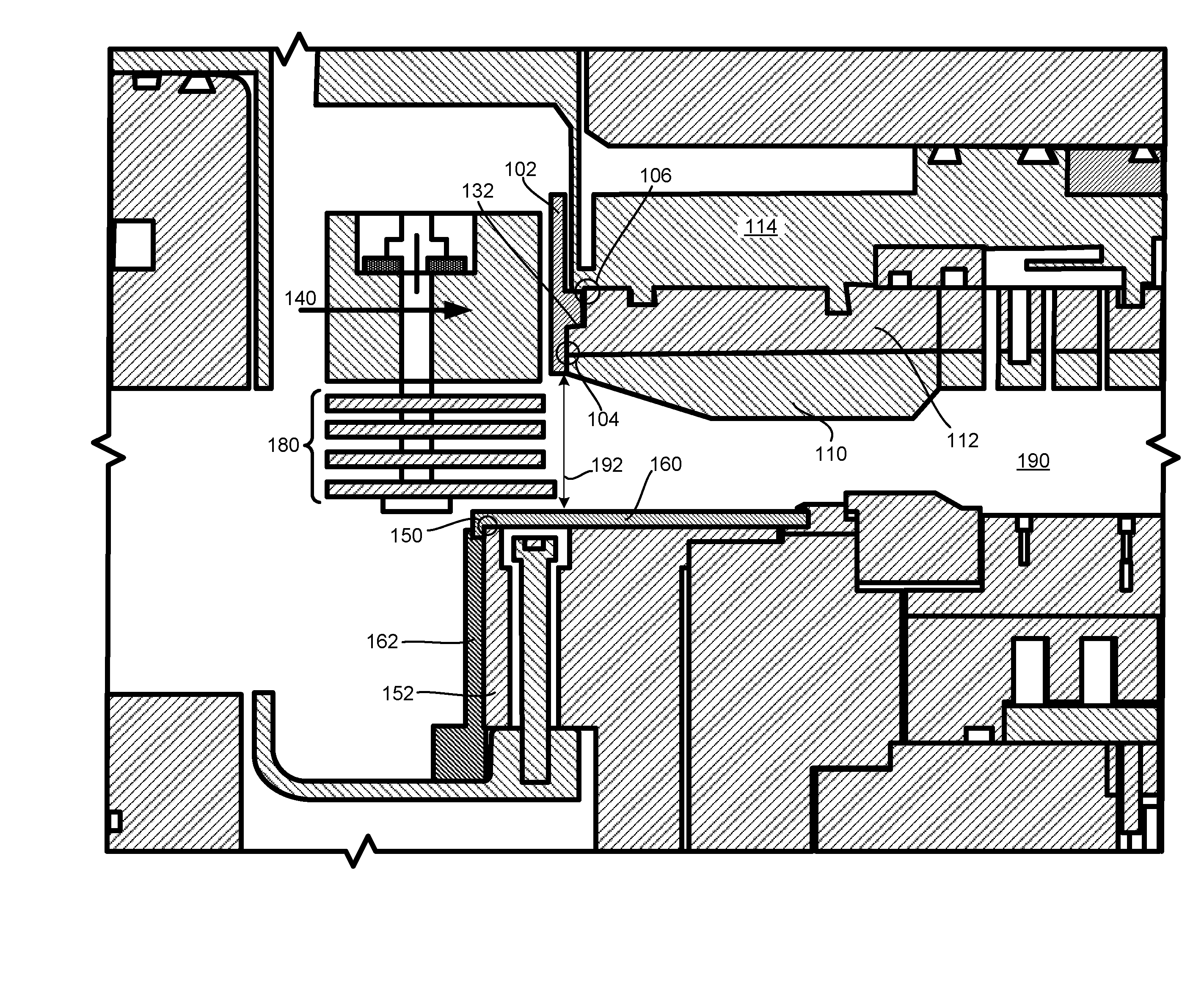
These sharp corners and surfaces themselves form gaps when adjacent RF chamber components are mated together, presenting high-impedance obstacles to the RF current.
Without wishing to be bound by theory, it is believed that in some cases, the high-impedance may cause a high voltage to be built up across a gap.
If the voltage is built up sufficiently high, a spark or arc may result across the gap.
Accordingly, the unintended injection of charged particles may lead to the unwanted ignition of plasma in the gas space(s) surrounding these gaps even though these gas space(s) are not in the aforementioned intended plasma generating region (e.g., the region generally defined by the upper electrode, the lower electrode, and the surrounding confinement rings).
When one of these unwanted ignition events occurs, the plasma chamber is said to be suffering a plasma un-confinement event, which is a highly undesirable condition for the substrate processing environment, for the substrate currently being processed, and may lead to damage to chamber hardware components, particularly to the electrostatic chuck.
Irrespective of the particulars of the different RF chambers, the RF current in many chambers tend to traverse multiple RF chamber components and tend to sporadically suffer from similar gap-related arcing and unwanted plasma ignition problems.

Method used


Image

  • Methods and apparatus for preventing plasma un-confinement events in a plasma processing chamber
  • Methods and apparatus for preventing plasma un-confinement events in a plasma processing chamber

Examples


Embodiment Construction

[0014]The present invention will now be described in detail with reference to a few embodiments thereof as illustrated in the accompanying drawing(s). In the following description, numerous specific details are set forth in order to provide a thorough understanding of the present invention. It will be apparent, however, to one skilled in the art, that the present invention may be practiced without some or all of these specific details. In other instances, well known process steps and / or structures have not been described.

[0015]In embodiments of the present invention, there are provided techniques and apparatus for substantially reducing and / or preventing the occurrence of plasma un-confinement events. As discussed, it is believed that aspects of the plasma chamber design and / or construction may contribute to the occurrence of arcing, leading to the unwanted ignition of plasma outside of the intended plasma sustaining region. As mentioned earlier, the inventors herein believe that ga...


PUM

PropertyMeasurementUnit
dielectricaaaaaaaaaa
dielectric shieldingaaaaaaaaaa
Debye lengthaaaaaaaaaa

Abstract

Techniques and apparatus for substantially reducing and / or preventing the occurrence of plasma un-confinement events, including one or more of shielding a gap disposed between chamber components and along a RF current path with a dielectric shielding structure, shielding a sharp component structure with a dielectric shielding structure, and keeping the gap between adjacent pairs of plasma confinement rings smaller than the worst-case DeBye length for the plasma.

Description

PRIORITY CLAIM[0001]This application incorporates by reference and claims priority under 35 USC 119(e) to a commonly-owned provisional application entitled “Methods and Apparatus for Preventing Plasma Un-confinement Events in a Plasma Processing Chamber”, filed by the same inventors herein on Jun. 8, 2006 (Application No. 60 / 804,278)BACKGROUND[0002]In the processing of a substrate, e.g., a semiconductor substrate or a glass panel such as one used in flat panel display manufacturing, plasma is often employed. As part of the processing of the substrate in a plasma chamber, the substrate is for example processed in a series of steps in which materials are selectively removed (etched) and deposited in order to form electrical components thereon.[0003]In an example chamber implementation based on an Exelan™ plasma processing system platform (available from Lam Research Corporation of Fremont, Calif.), RF energy is employed to ignite and sustain the plasma within the intended plasma susta...

Claims


Application Information

Patent Timeline
Patent Type & Authority Applications(United States)
IPC IPC(8): C23F1/00C23C16/00
CPCH01J37/32082Y10T29/49718H01J37/32623H01J37/32495C23C16/00H01L21/02365
Inventor FISCHERDHINDSA, RAJINDER
Owner LAM RES CORP
Learn More