Smart Solar Roof

a solar roof and solar energy technology, applied in sustainable buildings, light and heating equipment, machine operation modes, etc., can solve the problems of short working time in every geographical area, failure to completely expels all heat energy, and device failure to properly vent all heated air, etc., to achieve superior efficiency, high energy efficiency, and high efficiency rate

Inactive Publication Date: 2007-12-13
GRAVINA MATTEO B
View PDF37 Cites 0 Cited by
  • Summary
  • Abstract
  • Description
  • Claims
  • Application Information

AI Technical Summary

Benefits of technology

[0009]The advantage of the invention is its high rate of energy for use as potential energy. The high efficiency rate is an objective of the innovation, and that is to expel heat accumulated back to the ambient. The efficiency is superior to photovoltaic and solar concentrators. The ratio of the electrical energy consume to the rate of solar thermal energy it expels is over ten times for warm and hot climates.
[0010]An advantage is the energy it uses to the energy it produces. The practical application of the Invention is a two added energy innovation. Its heat absorption can be use to expel excess heat accumulated by roofs and roof attic. In addition, the use of heat as energy for several purposes can alleviate or reduce electricity or energy use by residential or commercial unit.
[0011]An advantage is the use of heat as energy. The use of capture heat in a control environment permits the user of this invention to use the energy content to heat water. In commercial use the heat can be utilize to heat water, ovens, or materials. When use as a solar energy collector the energy gain can be use for water heating in boilers, pool heating, or in industrial operations.
[0012]An advantage is the extra space accommodation it provides. By controlling the amount of heat a roof receives, an architect can also add additional space of a residential or commercial unit. The inner height of a roof can be elevated to accommodate extra space or produce additional cubic capacity.
[0013]A major advantage that is the most important factor is the invention is socially acceptable. The use of solar thermal concentrators that absorb the heat from the sun, and / or air, and sends it back, or makes use of it is acceptable. The unique way of expediting the overall process is socially acceptable because of the way it works. The process of working under the skin of a roof, without giving it an awkward view, makes this invention very attractive to home or commercial buyers of roofs.
[0014]An improvement of the invention over flat plate collector is wherein the ability to a) work under the skin of the outer envelope (roof shingle) hidden away from public view, and b) work from all angle as long as solar radiation is heating said roof, and 3) work without any interference from invention components.

Problems solved by technology

This mechanism does work for many residential and commercial units, but does come short of working in every geographical area.
It also falls short of completely expelling all the heat energy completely because it only sends heated air that it is able to capture.
This type of device fails to vent all the heated air properly by only grasping air that the turbine can reach.
It also fails by only working when wind is blowing.
Another failure in part by this method is the rotation of the turbine when heated air is wanted.
By ventilating the warm air within to the outside, it also brings unwanted cold air into the roof, making this device useless half of the time.
Although all methods are practical and do work under certain conditions, not one of them would work under all climatic and weather conditions.
Furthermore, the geographical locations of modern life make some of these methods impractical.
This form although very attractive for number of reasons, it falls short of efficiency.
The overall efficiency of any type of Photovoltaic is very low; no panel is able to have efficiency above thirty percent in the market.
On the other hand, solar thermal collectors do have a higher efficiency than Photovoltaic, but they also fall short when location is a factor.
These two types of systems although do serve a simple task, they do lack in efficiency and attractiveness.
Many consumers find any obscure or alteration of their roof awkward.

Method used


Image

  • Smart Solar Roof
  • Smart Solar Roof
  • Smart Solar Roof

Examples


Embodiment Construction

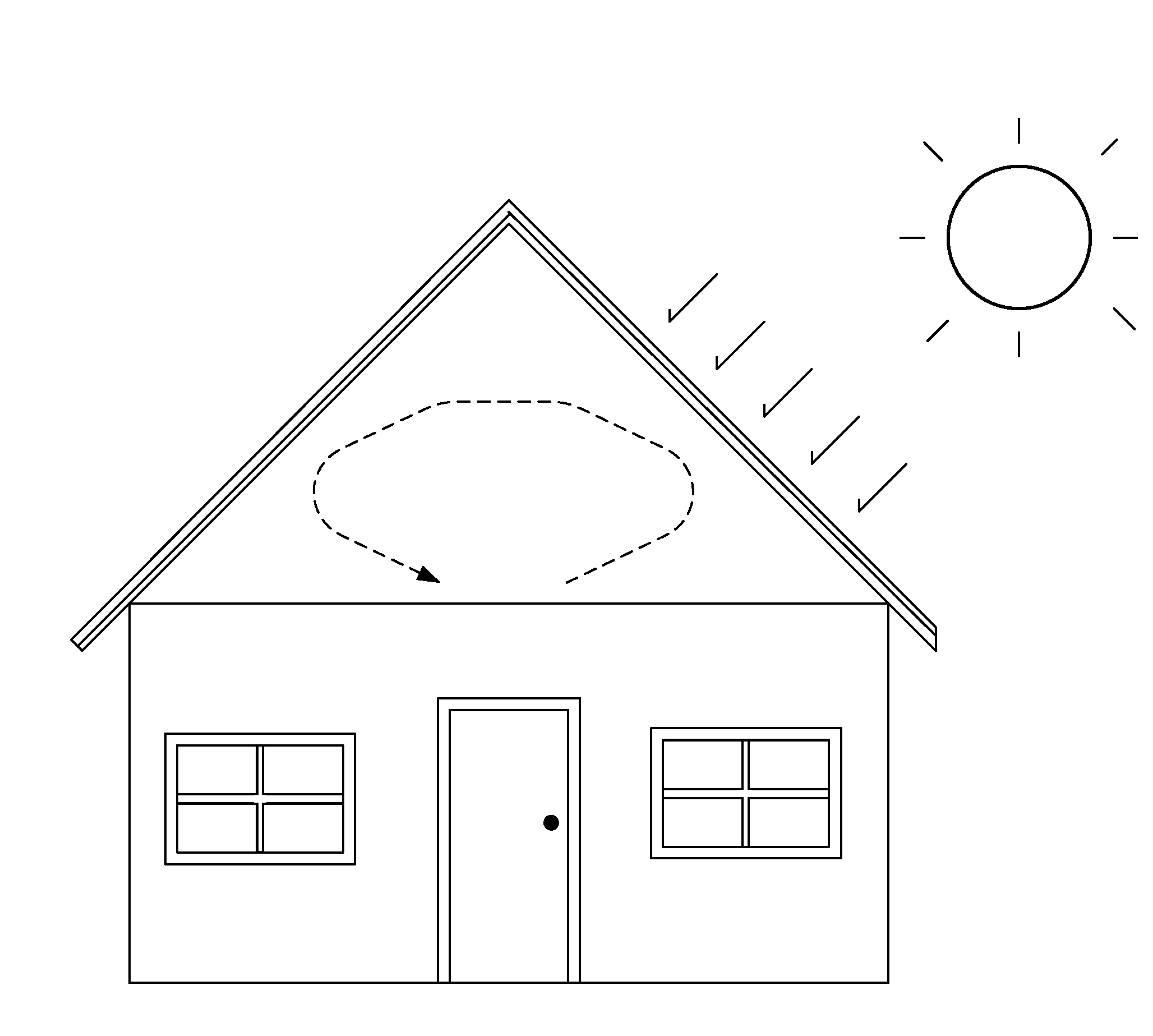
[0018]In the embodiment shown in FIG. 1, the invention shown as an expression how a typical housing unit circulates unwanted heated air inside a typical roof. Typical of housing units most of the air circulates and encapsulates by the incoming radiation. This circulation of heated air increases dramatically a heat bubble within.

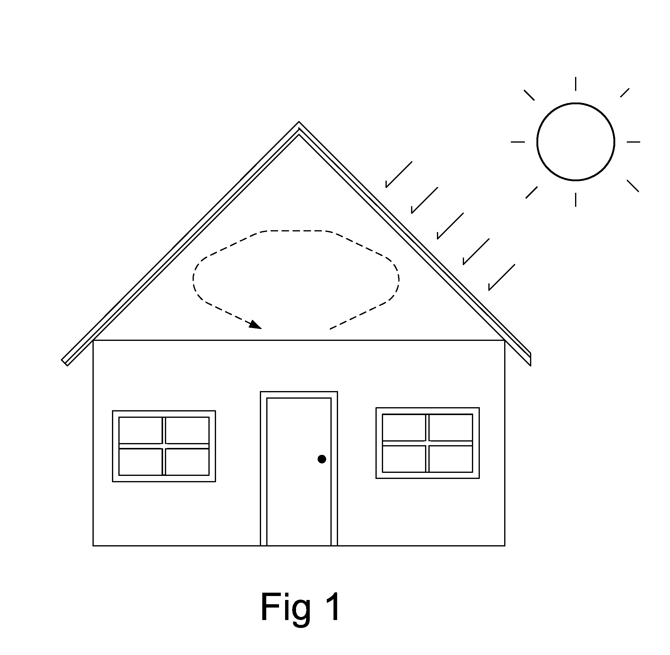
[0019]FIG. 2 illustrates a bi-level frame constructed below the roof top material. The illustration shows how the upper level metal sheet (1) would receive the incoming radiation by conduction to the inside into its conduit of which it would be supported by inner supporting column (3) which are themselves supported by the lower level metal sheet (2).

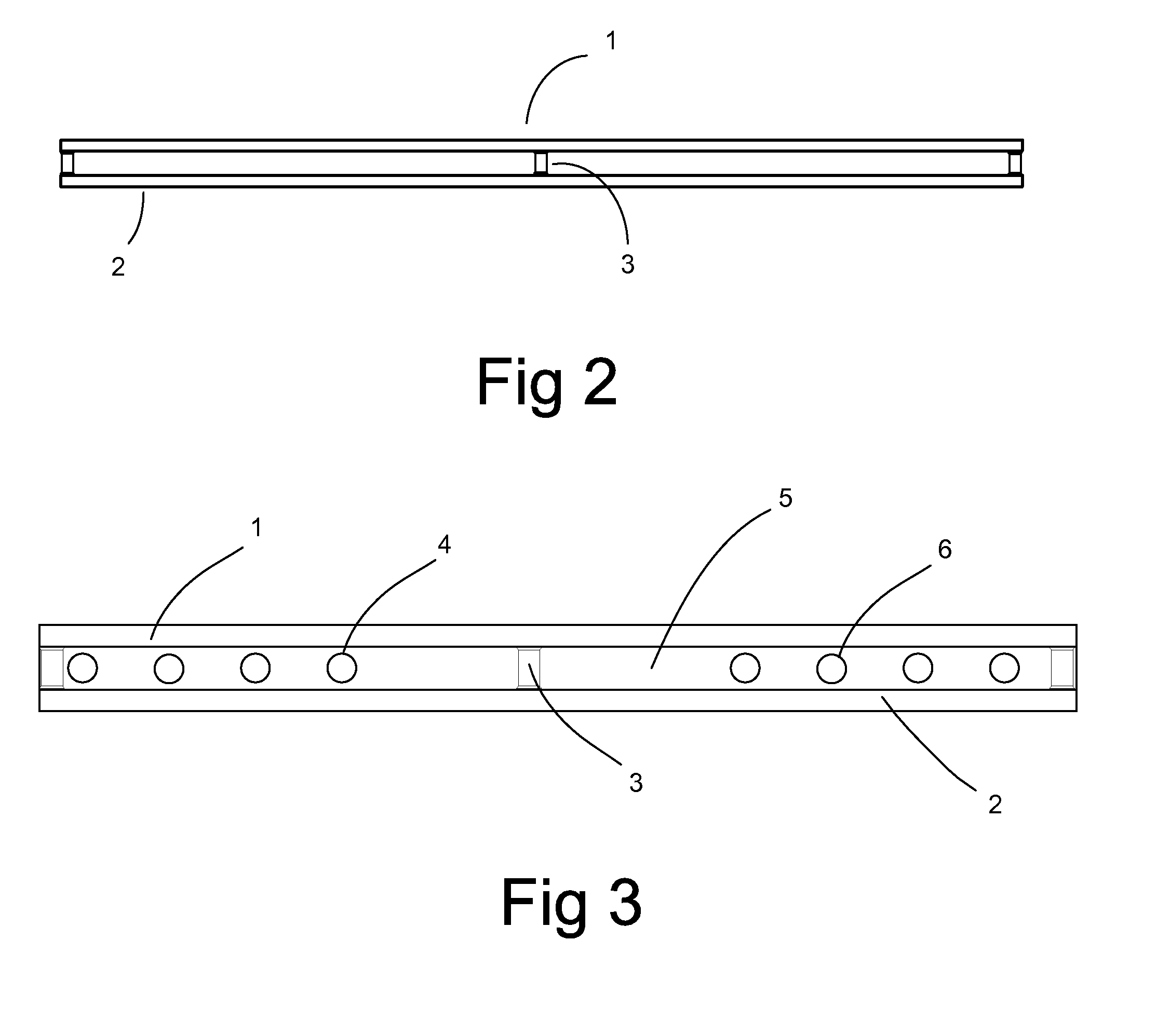
[0020]FIG. 3 illustrates a cross section view between the upper metal sheet (1) and the lower metal sheet (2) with a view of an intersecting rail (5) with pump-to-chamber perforations (4) that allow for a continual flow of air through the chambers. The inner supporting columns (3) restrict free flow of air thus on...


PUM


Abstract

A heat pump use for expelling solar thermal energy by electromechanically transferring heat to a major component and continuously expels it from an upper level of a static structure. The invention receives and transfer solar thermal energy between two metal sheets that restricts heat and by means of airflow heat energy is transfer to a condensing unit. Solar energy is thereby expelled out into the ambient conventionally by means of airflow from a condensing unit draining system.

Description

FIELD OF THE INVENTION[0001]The present invention relates to energy preservation roofs, particularly to an invention for the preservation and the efficient use of energy. A hybrid between two types of devices, it is first an energy cooling system that retransfers solar radiation, and secondly it ventilates this energy.BACKGROUND OF THE INVENTION[0002]Inventions for practical conservation and use of energy are known in the roof industry. The roof industry has come up with elaborate designs and materials that help a building unit use less cooling or heating energy. Other devices that brought to the forefront are passives solar, and active solar devices that make use of solar radiation.[0003]The traditional uses of air conditioning for residential and commercial units are the use of ceiling fans, heat pumps, and window units. Outside the house ventilation equipment reduce the amount of heat energy entering a unit. The applications of ventilation fans help reduce the amount of solar ene...

Claims


Application Information

Patent Timeline
Patent Type & Authority Applications(United States)
IPC IPC(8): F25B29/00
CPCF24J2/045Y02E10/44Y02B10/20F24J2/30F24S20/67F24S10/30Y02A30/60
Inventor GRAVINA, MATTEO BONIFACIO
Owner GRAVINA MATTEO B
Why Eureka
Try Eureka