Heat Recycling System for Use with a Gasifier

a gasifier and heat recycling technology, applied in the details of gasification processes, combustion processes, combustible gas production, etc., can solve the problems of insufficient attention of prior systems and processes, less desirable disposal of waste materials by incineration, etc., to maximize energy production, minimize process energy consumption, and optimize gasification process efficiency

Inactive Publication Date: 2007-12-13
PLASCO ENERGY GROUP INC
View PDF35 Cites 36 Cited by
  • Summary
  • Abstract
  • Description
  • Claims
  • Application Information

AI Technical Summary

Benefits of technology

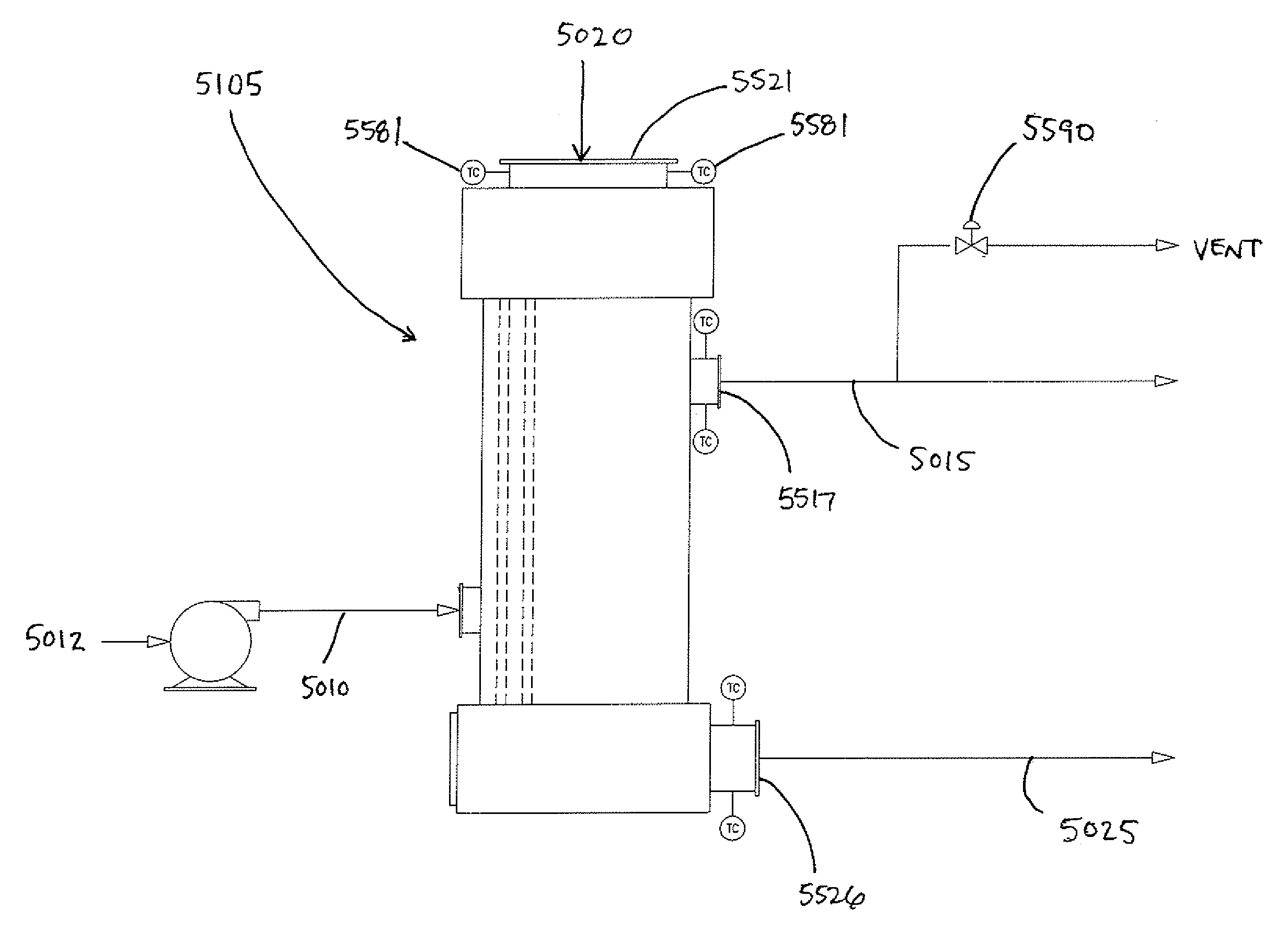
[0021] In accordance with one embodiment of the invention, the system also comprises a control system comprising sensing elements for monitoring operating parameters of the system, and response elements for adjusting operating conditions within the system to optimize the gasification process, wherein the response elements adjust the operating conditions within the system according to the data obtained from the sensing elements, thereby optimizing the efficiency of a gasification process by minimizing energy consumption of the process, while also maximizing energy production.
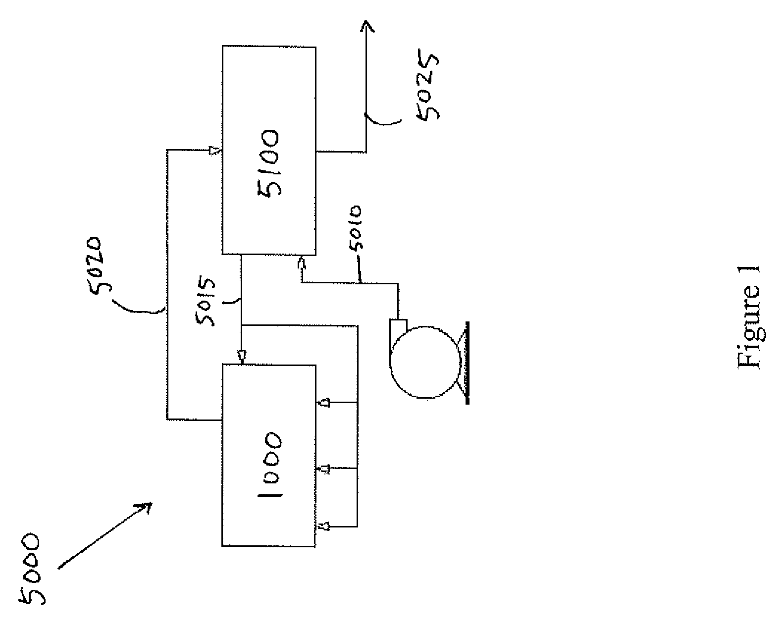
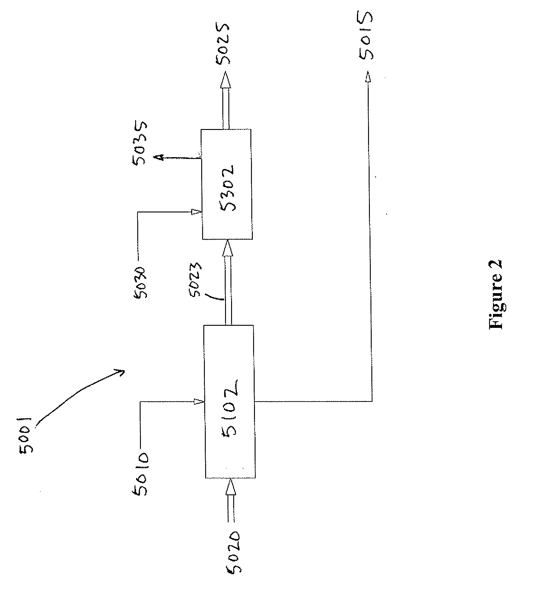
[0022] In accordance with one aspect of the invention, there is provided a process for improving the efficiency of a carbonaceous feedstock gasification process by recycling sensible heat from a hot gas produced by the gasification process back into the gasification process using a gas-to-fluid heat exchanger, the process comprising the steps of passing the hot product gas through the gas-to-fluid heat exchanger, passing the cool fluid through the gas-to-fluid heat exchanger, transferring heat from the hot product gas to the cool fluid via the gas-to-fluid heat exchanger to produce a cooled product gas which exits the heat exchanger via a cooled product gas outlet, and a heated fluid which exits the heat exchanger via a heated fluid outlet, and using the heated fluid to provide heat for the carbonaceous feedstock gasification process.

Problems solved by technology

It is becoming less desirable to dispose of waste material by incineration because of the extreme waste of fuel in the heating process and the further waste of disposing, as a residual waste, material that can be converted into a useful syngas and solid material.
The gas produced during the gasification of carbonaceous feedstock is usually very hot but may contain small amounts of unwanted compounds and requires further treatment to convert it into a useable product.
Prior systems and processes have not adequately addressed the problems that must be dealt with on a continuously changing basis.

Method used


Image

  • Heat Recycling System for Use with a Gasifier
  • Heat Recycling System for Use with a Gasifier
  • Heat Recycling System for Use with a Gasifier

Examples


example

[0209] In general, the system of the present invention is used by feeding exchange-air into a converter where feedstock is subjected to sufficient heat to allow the gasification reaction to take place.

[0210] In the exemplary embodiments depicted in FIG. 12 and 13, the gasifiers 2100 and 2200 each have stepped floors having three floor levels, or steps. Optionally, each floor level is sloped between about 5 and about 10 degrees. In a step-floor gasifier, the individual steps (floor levels) provide conditions appropriate for the respective drying, volatilization and char-to-ash conversion stages of the gasification process, to thereby allowing for the optimization of the gasification process.

[0211] In each of these exemplary gasifiers, the feedstock is fed onto the first step, where the conditions are provided such that the major process here is that of drying, with some volatilization and char-to-ash conversion. The normal temperature range for this step (as measured at the bottom ...


PUM

PropertyMeasurementUnit
temperatureaaaaaaaaaa
pressuresaaaaaaaaaa
temperatureaaaaaaaaaa

Abstract

The present invention provides a system that recycles heat recovered from hot products of a carbonaceous feedstock gasification process back into the gasification process. The hot gaseous products are used to heat working fluids such as air and water to produce hot air, hot water or steam. The heated fluids are used to return heat back to the gasification process. The system also comprises a control system to optimize the efficiency of a gasification process by minimizing energy consumption of the process, while also maximizing energy production.

Description

CROSS REFERENCE TO RELATED APPLICATIONS [0001] This application claims benefit of priority under 35 U.S.C. §119(e) from U.S. Provisional Application Ser. No. 60 / 746,612, filed May 5, 2006. This application also claims benefit of priority to International Patent Application No. PCT / CA2006 / 000881, filed Jun. 5, 2006. This application also claims benefit of priority under 35 U.S.C. §119(e) from U.S. Provisional Application Ser. No. 60 / 864,116, filed Nov. 2, 2006. This application also claims benefit of priority under 35 U.S.C. §119(e) from U.S. Provisional Application Ser. No. 60 / 911,179, filed Apr. 11, 2007. This application also claims benefit of priority under 35 U.S.C. §119(e) from U.S. Provisional Application Ser. No. 60 / 797,973, filed May 5, 2006. The contents of all of the aforementioned applications are hereby expressly incorporated by reference in their entirety and for all purposes.FIELD OF THE INVENTION [0002] This invention relates to the gasification of carbonaceous feedst...

Claims


Application Information

Patent Timeline
Patent Type & Authority Applications(United States)
IPC IPC(8): F24D1/00C10J1/207
CPCC10J3/002C10J3/48C10J2300/1869C10J2300/1884Y02E20/12F23G5/027F23G5/46F23G2206/10C10J2300/1892C10J3/24C10J3/723C10J3/82C10J2200/09F23G5/50Y02P20/129F24D1/00
Inventor TSANGARIS, ANDREASSWAIN, MARGARET
Owner PLASCO ENERGY GROUP INC
Why Eureka
Try Eureka