Control circuit to reduce reverse current of synchronous rectifier

Active Publication Date: 2007-12-13
SEMICON COMPONENTS IND LLC
View PDF2 Cites 5 Cited by
  • Summary
  • Abstract
  • Description
  • Claims
  • Application Information

AI Technical Summary

Benefits of technology

[0006]The present invention provides a control circuit to reduce a reverse current of a synchronous rectifier. A predication circuit is utilized to generate a timing signal in accordance with a control signal and a switching signal. The on time of the switching signal represents the charge time of an inductor of a power converter. The timing signal is applied to turn off the synchronous rectifier of the

Problems solved by technology

However, these current sensing circuit cause power loss and add complexity to the system.
Moreover, t

Method used


Image

  • Control circuit to reduce reverse current of synchronous rectifier
  • Control circuit to reduce reverse current of synchronous rectifier
  • Control circuit to reduce reverse current of synchronous rectifier

Examples


Embodiment Construction

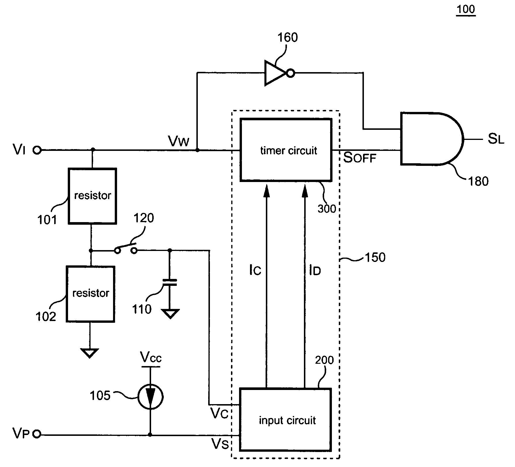
[0019]FIG. 6 shows a circuit diagram of a preferred embodiment of a power converter in accordance with present invention. The power converter is used to provide the output voltage VO to a load 51. A control circuit 100 is coupled to receive a switching signal VW and generate a drive signal SL to control a switch 21. The switch 21 is coupled from an inductor 31 to a ground to provide a low-impedance current path for the inductor 31 as long as the discharge current of the inductor 31 is existed. The switch 21 is operated as a synchronous rectifier. A capacitor 41 is coupled to the inductor 31. An input terminal VI of the control circuit 100 connects to receive the switching signal VW. A program terminal VP of the control circuit 100 is coupled to a resistor 70 connected to the ground to program a control signal VS for predicting the discharge time of the inductor 31 and producing the drive signal SL. The control signal VS can be programmed in accordance with the output voltage VO of t...


PUM


Abstract

The present invention provides a control circuit to avoid a reverse current of a synchronous rectifier. A switching signal is applied to charge an inductor of a power converter. A predication circuit generates a timing signal in response to the switching signal. The timing signal is used to turn off the synchronous rectifier for preventing the reverse current occurred in light load and no load conditions.

Description

FIELD OF INVENTION[0001]The present invention relates in general to power converter, and more particularly, to the control circuit of power converter.BACKGROUND OF THE INVENTION[0002]Power converters are used to convert an unregulated power source to a regulated voltage and / or current source. FIG. 1 shows a traditional power converter with synchronous rectification. A switching signal S1 is utilized to control the duty cycle of a switch 10 for the regulation of the output voltage VO. The output voltage VO is provided to a load 50. A charge current will charge an output capacitor 40 during the on time of the switch 10. FIG. 2 shows a switching signal S2 to enable a switch 20 in response to the off-state of the switch 10 to provide a low impedance current path for a discharge current IF of the inductor 30. A switching signal VW is applied to charge the inductor 30 once the switch 10 is turned on.[0003]In continuous current mode (CCM) operation, the switch 10 is turned on before the en...

Claims


Application Information

Patent Timeline
IPC IPC(8): G05F1/00
CPCH02M1/08Y02B70/1466H02M3/1588Y02B70/10
Inventor YANG, TA-YUNG
Owner SEMICON COMPONENTS IND LLC
Why Eureka
Try Eureka