Step frequency high resolution radar

a high-resolution radar and step frequency technology, applied in the direction of reradiation, measurement devices, instruments, etc., can solve the problems of expensive and complex radar systems, limited long-range performance, and inability to fly such transmitters on aircraft. , to achieve the effect of low cost, low cost and low cos

a high-resolution radar and step frequency technology, applied in the direction of reradiation, measurement devices, instruments, etc., can solve the problems of expensive and complex radar systems, limited long-range performance, and inability to fly such transmitters on aircraft. , to achieve the effect of low cost, low cost and low cos

US20070285302A1Active Publication Date: 2007-12-13TELEPHONICS

Image

  • Step frequency high resolution radar
  • Step frequency high resolution radar
  • Step frequency high resolution radar

Examples


Embodiment Construction

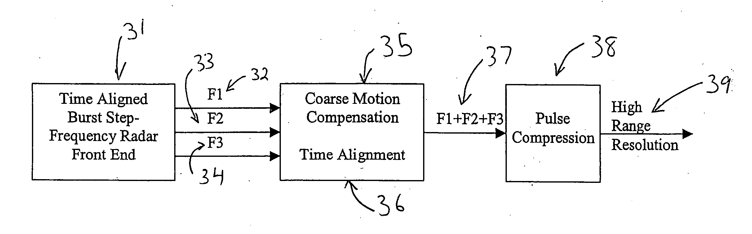
[0028] In the present invention a transmitter is employed to broadcast a frequency-modulated probe signal at each of a number of frequency steps. A receiver receives a return signal from which magnitude and phase information corresponding to a target object are measured and stored in a memory at each of the center frequency steps. The range to the object is determined using the set of magnitude and phase information stored in the memory. The present invention uses a number of narrow bandwidth pulses instead of a large broad band pulse to determine the location of a target.

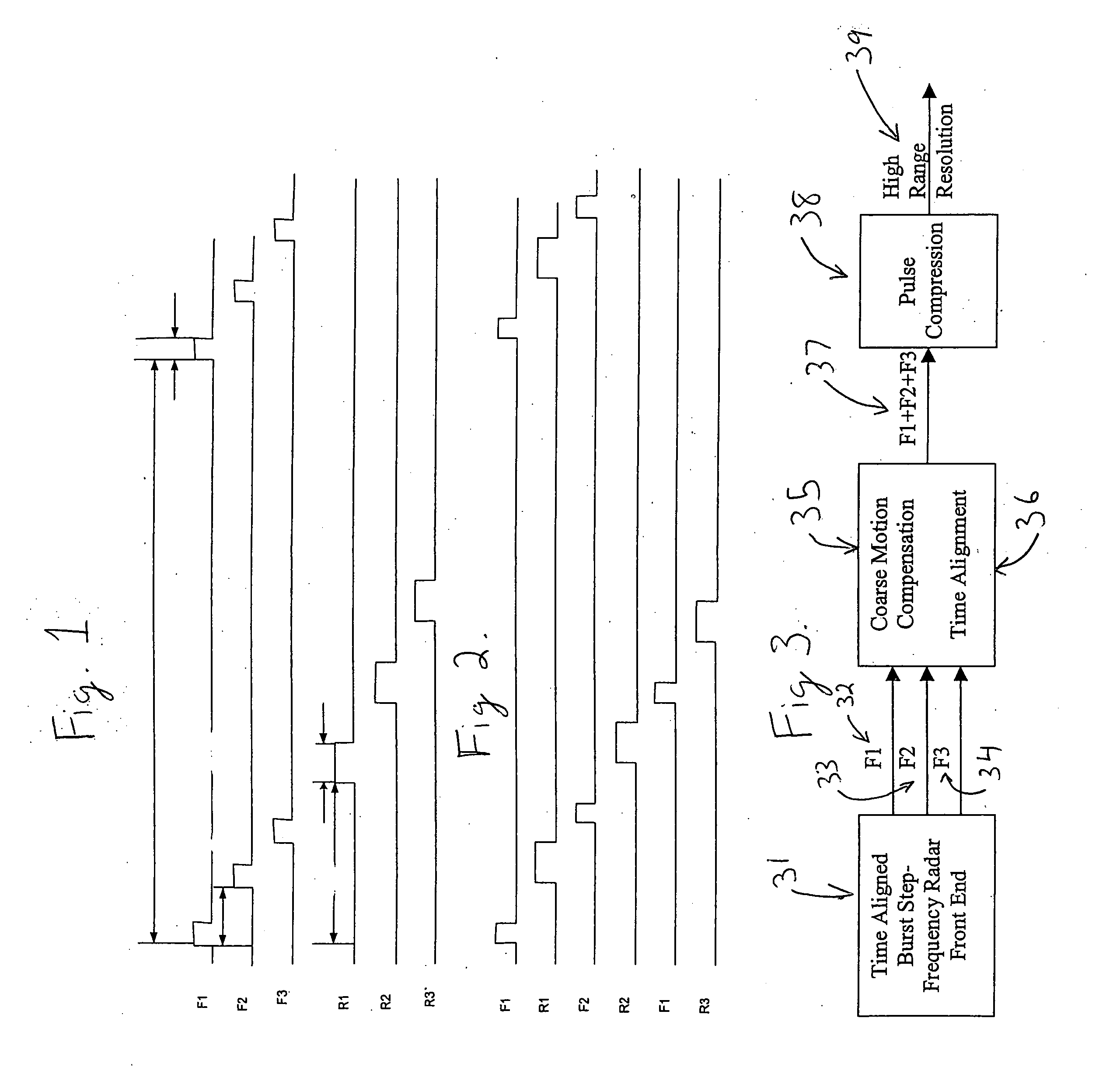
[0029]FIG. 1 illustrates the present invention being used to locate a target at a long range. The pulses F1, F2, and F3 represent a series of pulses emitted by a radar system utilizing the present invention. The pulses R1, R2, and R3 represent the pulses returning to the detector after bouncing off the target. All the F pulses in the initial emission are transmitted in a series of short bursts before any of the R ...


PUM


Abstract

The present invention is directed to an improved radar system that produces high range resolution while using existing narrow processing bandwidths and sampling rates to achieve a low cost radar product that is particularly useful for moving targets. The present invention uses a small number of closely spaced Linear Frequency Modulated Chirps. In one embodiment typically 2, 3, 4 chirps are used. Each frequency is sampled at a rate commensurate with the narrower bandwidth, corrected for motion (Time Aligned) and combined to produce a single wide-band chirp but achieved using the lower sample rate commensurate with the narrower transmitted waveform.

Description

[0001] This is a conversion of U.S. Provisional Application Ser. No. 60 / 603,742, filed Aug. 23, 2004, the disclosures of which are incorporated herein by reference.FIELD OF THE INVENTION [0002] The present invention relates to improvements in coherent high range resolution imaging applications including but not limited to Strip Map, Spot SAR and ISAR. BACKGROUND OF THE INVENTION [0003] In many radar applications it is necessary to form two-dimensional images of targets such as ground vehicles, aircraft, ships, and so forth. Resolution in one dimension is provided by the range resolution inherent in the transmit waveform, and resolution in the other cross range dimension is provided by Doppler resolution. The principles are widely applicable and widely applied. Synthetic aperture radar (SAR) forms two-dimensional images in range and cross range with the cross range dimension utilizing the motion of the platform for Doppler resolution. Inverse synthetic aperture radar (ISAR) is accomp...

Claims


Application Information

Patent Timeline
13 Dec 2007
Publication
US20070285302A1
IPC
G01S13/90
CPC
G01S13/9035; G01S13/282; G01S13/9019; G01S13/904
Inventors
AARSETH, CRAIG; WAHL, ROBERT