Deflecting Plate and Liquid Crystal Display Device

a technology of liquid crystal display device and deflector plate, which is applied in the direction of instruments, polarising elements, electrical equipment, etc., can solve the problems of insufficient surface hardness of polarizer plate protective film, and high flexural modulus of polymer exhibiting high surface hardness, etc., to achieve excellent tenacity and surface hardness, low flexural modulus, and high flexural modul

Active Publication Date: 2007-12-13
ZEON CORP
View PDF28 Cites 49 Cited by
  • Summary
  • Abstract
  • Description
  • Claims
  • Application Information

AI Technical Summary

Benefits of technology

[0006] The inventors of the present invention have conducted extensive studies in order to achieve the above object. As a result, the inventors have found that a polarizer plate having a polarizer protection function and exhibiting excellent tenacity and surface hardness can be obtained by stacking a layer including a thermoplastic

Problems solved by technology

In general, a polymer exhibiting high surface hardness has a high flexural modulus, but is fragile.
Therefore, when using a polymer exhibiting high surface hardness as the material for the polarizer plate protective film, cracks tend to occur when forming the polarizer plate.
On the other hand, when using a polymer exhibiting high tenacity as the material for the polarizer plate protective film, the resulting polarizer plate protective film exhibits i

Method used


Image

  • Deflecting Plate and Liquid Crystal Display Device
  • Deflecting Plate and Liquid Crystal Display Device
  • Deflecting Plate and Liquid Crystal Display Device

Examples


example 1

(1) Production of Transparent Film (A1) Forming Protective Layer A

[0150] PMMA was supplied to a hopper provided to a double-flight 50-mm single-screw extruder (ratio of screw effective length L to screw diameter D (L / D)=28) equipped with a leaf-disk polymer filter with a pore diameter of 10 μm. The molten resin was supplied to a multi-manifold die with a die lip surface roughness Ra of 0.1 μm at an extruder exit temperature of 260° C. and an extruder gear pump rotational speed of 12 rpm.

[0151] NB was supplied to a double-flight 50-mm single-screw extruder (L / D=30) equipped with a leaf-disk polymer filter with a pore diameter of 10 μm. The molten resin was supplied to a multi-manifold die with a die lip surface roughness Ra of 0.1 μm at an extruder exit temperature of 260° C. and an extruder gear pump rotational speed of 6 rpm.

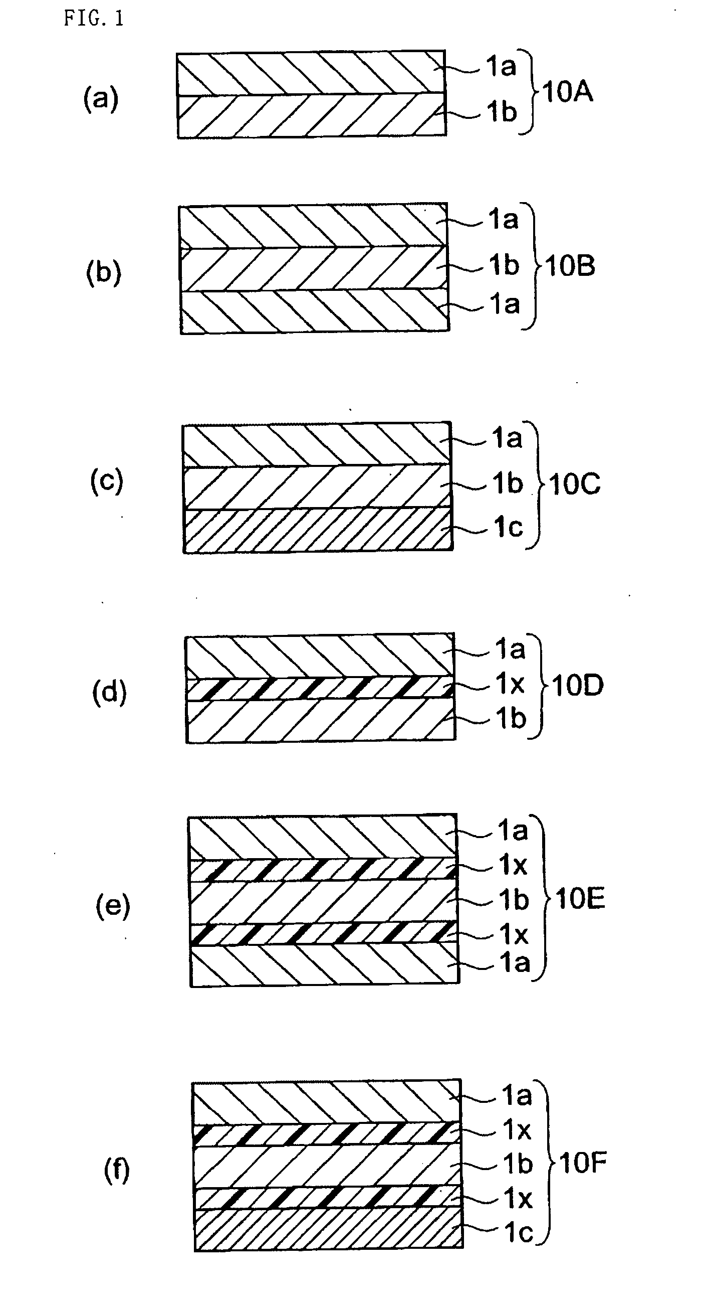
[0152] The molten PMMA (layer a), NB (layer b), and EVA (adhesive layer=layer x) were discharged from the multi-manifold die at 260° C. and cast onto a chil...

example 2

[0164] A coextruded transparent film (A2) with a width of 600 mm and a thickness of 100 μm formed of layer a (20 μm)-layer x (4 μm)-layer b (52 μm)-layer x (4 μm)-layer a (20 μm) was obtained in the same manner as in Example 1 except for using PS as the resin a instead of PMMA. A polarizer plate was produced and installed in a liquid crystal monitor in the same manner as in Example 1.

example 3

[0165] A coextruded transparent film (A3) with a width of 600 mm and a thickness of 100 μm formed of layer a (30 μm)-layer x (4 μm)-layer b (66 μm) was obtained in the same manner as in Example 1 instead of a five-layer transparent film formed of three types of layers. A polarizer plate was produced and installed in a liquid crystal monitor in the same manner as in Example 1 so that the layer a was disposed on the viewer side.


PUM


Abstract

The present invention provides a polarizer plate including at least a protective layer A, a polarizer, and a protective layer B in that order, the protective layer A including at least layers a and b respectively including a thermoplastic resin as a main component, the layer a having a flexural modulus higher than that of the layer b; and a liquid crystal display device including a light source, an incident-side polarizer plate, a liquid crystal cell, and an exit-side polarizer plate in that order, the incident-side polarizer plate and/or the exit-side polarizer plate being the polarizer plate of the present invention. According to the present invention, a polarizer plate exhibiting high tenacity and high surface hardness and a liquid crystal display device including the polarizer plate are provided.

Description

TECHNICAL FIELD [0001] The present invention relates to a polarizer plate exhibiting high tenacity and high surface hardness, and a liquid crystal display device including the polarizer plate and a liquid crystal cell. BACKGROUND ART [0002] In related-art technology, a polarizer plate protective film is bonded to each side of a polarizer in order to improve the durability of the polarizer. The polarizer plate protective film is required to exhibit high tenacity and high surface hardness. In general, a polymer exhibiting high surface hardness has a high flexural modulus, but is fragile. Therefore, when using a polymer exhibiting high surface hardness as the material for the polarizer plate protective film, cracks tend to occur when forming the polarizer plate. On the other hand, when using a polymer exhibiting high tenacity as the material for the polarizer plate protective film, the resulting polarizer plate protective film exhibits insufficient surface hardness. Therefore, a known ...

Claims


Application Information

Patent Timeline
IPC IPC(8): G02F1/1335G02B5/30
CPCG02B1/105G02B5/3083G02F1/133528G02B5/305G02B1/14G02F1/1335G02F1/133502B32B2457/20
Inventor TOYOSHIMA, TETSUYAARAKAWA, KOUHEI
Owner ZEON CORP
Why Eureka
Try Eureka