
Auto Distinction System And Auto Distinction Method

Inactive Publication Date: 2007-12-13
DAICEL CHEM IND LTD
View PDF2 Cites 13 Cited by
  • Summary
  • Abstract
  • Description
  • Claims
  • Application Information

AI Technical Summary

Benefits of technology

[0026] In the present invention, since a characteristic information (defect information) about an assembled fiber band can be efficiently extracted, even from a continuously moving assembled fiber band, the quality of the assembled fiber band can be accurately distinguished with time by accurately extracting the defective portions or the uneven portions of the assembled fiber band. Moreover, the present invention ensures to detect not only a single characteristic of the assembled fiber band, but also a defect information with respect to at least two characteristics selected from a width, a thickness, and a stain. Furthermore, even in the case of a band-shaped assembled fiber band such as a filter tow which moves at a high speed, fluctuations in width and thickness and stains can be efficiently detected. Furthermore, not only can defective portions be distinguished by the system by itself, but also the characteristic information is sent to a computer (for example, a process control computer) and analyzed by the computer as a time sequence fluctuation information, whereby the information can be used for process control and quality control at a production site (point of production).
[0027] Further, since the system can process the video signal as an analog signal, it is unnecessary to digitize the signal by an A / D conversion means and it is unnecessary to have a memory for temporarily storing the video signal. Moreover, two thresholds for the analog signal are set by electronic circuits of the system to perform such a distinction that a signal is not considered as a measuring object when the signal is over either of the thresholds, with a high speed in real time. In addition, an advanced processing such as selection and sorting of a measuring object can be conducted. Further, the result of distinction can be informed the outside. Furthermore, an improved distinction can be realized without using a computer.

Problems solved by technology

However, this device requires a plurality of light sources and a plurality of imaging means.
However, when these systems are applied to an assembled fiber band which is continuously moving or running, it becomes difficult to accurately detect defects such as stains and unevenness of thick or thin portions, because not only does an inspection target continuously move, but also the width and thickness of the assembled fiber band fluctuate by continuous moving.
Accordingly it becomes difficult to accurately detect defects (or uneven portions) of the assembled fiber band or the fiber pieces.
Accordingly, the formation tester can neither efficiently nor quickly distinguish suitability (or appropriateness) of a defect information of an assembled fiber band sequentially.
Accordingly, suitability of the defect information concerning the assembled fiber band cannot be distinguished efficiently with a high accuracy in time series.
Therefore, the method cannot conduct an advanced processing such as selection and sorting of a measuring object, and in addition, requires a computer.

Method used


Image

  • Auto Distinction System And Auto Distinction Method
  • Auto Distinction System And Auto Distinction Method
  • Auto Distinction System And Auto Distinction Method

Examples


Embodiment Construction

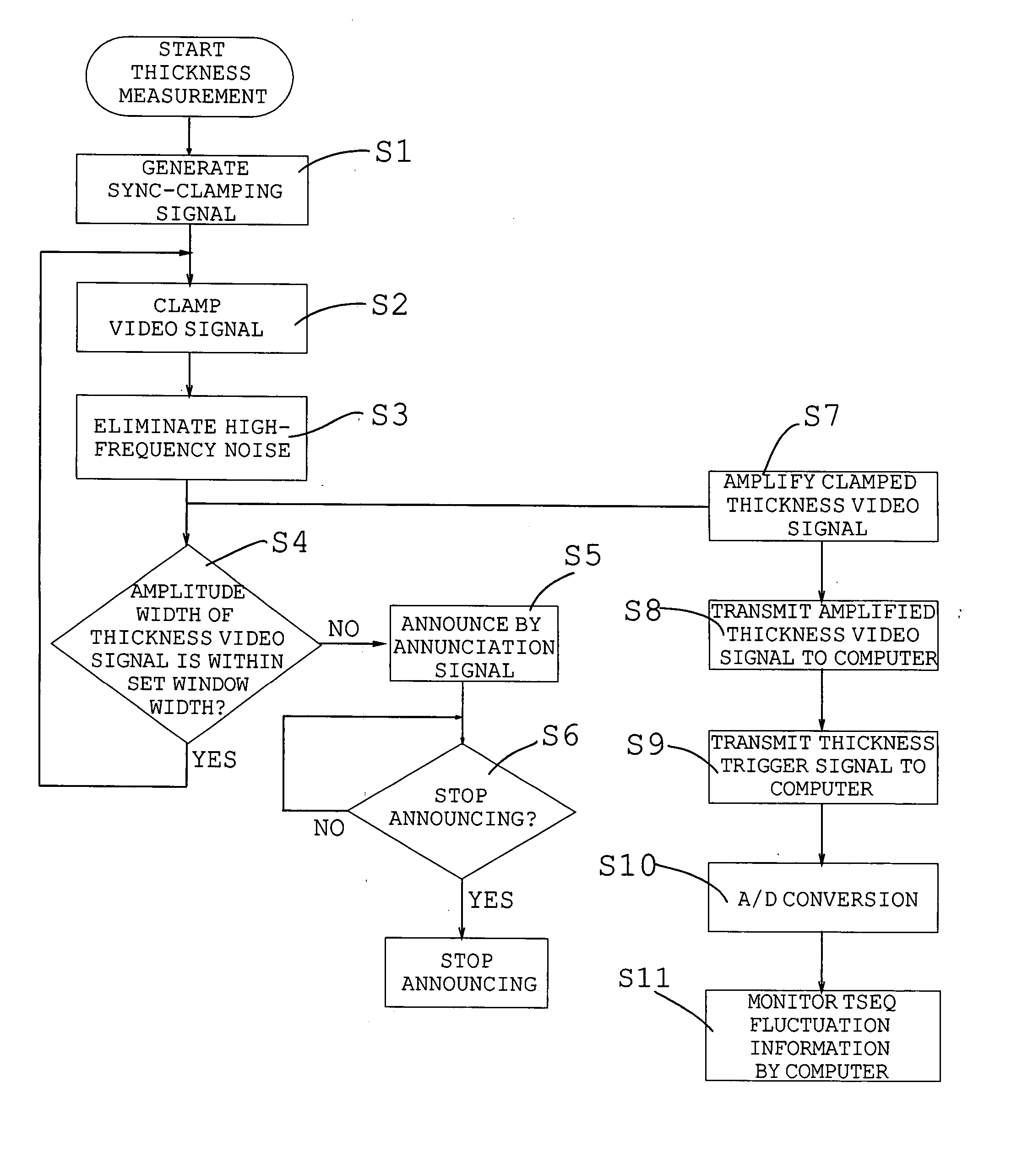
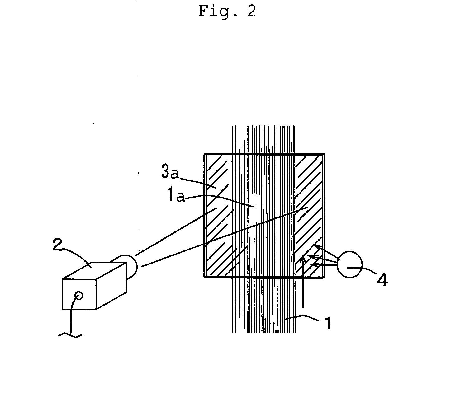
[0044]FIG. 1 is a block diagram showing an example of the electrical construction of the system of the present invention, FIG. 2 is a schematic layout drawing of the system of FIG. 1, and FIG. 3 is a flowchart for illustrating operations of the system of FIG. 1. In this example, thickness (or uneven thickness) of a filter tow (a band-shaped tow) which continuously moves is detected. The filter tow (or the tow band) comprises a plurality of yarns. Namely, the filter tow is formed of a plurality of yarns which are bundled, adjacently arrayed each other and overlapped to form a layer form. Therefore, the degrees of adjacency and overlapping of the yarns fluctuate while yarns are moving, and unevenness in thickness of the filter tow easily generates a defective product.

[0045] As shown in FIG. 2, on the foreside of a filter tow 1 which is continuously moving from the lower side to the upper side, a line sensor (imaging means) 2 is disposed with a predetermined angle of view, and on the ...


PUM


Abstract

The present invention provides an auto distinction system and an auto distinction method with which suitability of a width, a thickness, and a stain of a continuously moving assembled fiber band can be accurately distinguished. An assembled fiber band such as a filter tow which continuously moves on the front side of a background plate is imaged by a line sensor. Based on the produced video signal, a characteristic information containing a defect information concerning a thickness, a width, and a stain of the assembled fiber band is detected, and the defect information is extracted from the characteristic information. Thus suitability of the assembled fiber band is distinguished. For example, the video signal is supplied to a noise-eliminating circuit 6a and a defect signal concerning the thickness of the assembled fiber band is extracted. Based on the extracted signal and a reference signal with respect to the information, suitability of the defect information is distinguished by a distinction circuit 7. When the results of distinction are defective, the results are announced by an annunciation circuit 8. The video signal may be clamped by a clamping circuit 5b, and based on the clamped video signal, the defect information of the assembled fiber band may be extracted. The characteristic information or the defect information may be supplied to an external computer and used for process control.

Description

TECHNICAL FIELD [0001] The present invention relates to an auto distinction system which detects a characteristic information including a defect information of a continuously moving assembled fiber band (for example, a fiber bundle or a fiber assembly such as a filter tow) and which is useful for quality control of the assembled fiber band with time on the basis of the defect information or time sequence (TSEQ) fluctuation information; and relates to an auto distinction method. BACKGROUND ART [0002] A video signal (an image signal) from an imaging means is used for quality control and distinguishing whether an inspection target is non-defective or defective. For example, the specification of Japanese Patent No. 3013903 (Patent Document 1) discloses a defect-sensing device for detecting a defect on edges of a flat glass having seaming surfaces obtained by chamfering the edges, in which the device detects on the edges of the glass placed horizontally; wherein the device comprises a li...

Claims


Application Information

Patent Timeline
IPC IPC(8): G01N21/88
CPCD01G31/006G01N21/898G01N21/892G01B11/024D06H3/08G01B11/02
Inventor KANEDA, HIROSHITAKEBE, MASAKI
Owner DAICEL CHEM IND LTD
Learn More